Fundamental and Symmetrical Components
The fundamental components are calculated from the frequency-tracked instantaneous values through a
Fourier filter (integration interval: one period). The results are phasor values that are described by way of the
amount and phase angle.
In accordance with the transformation matrix, the symmetrical components are calculated from the voltage
and current phasors. These are also phasor quantities.
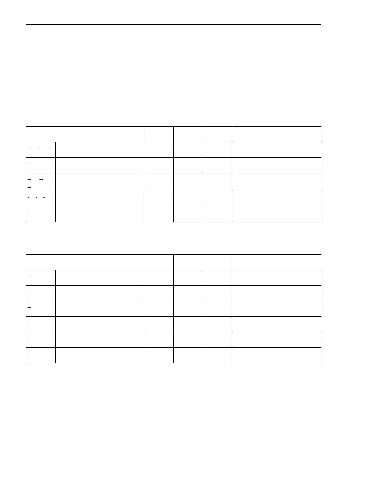
Fundamental Components
Table 9-2 Fundamental Components
Values Primary Secon-
dary
Phase
Angle
% Referenced to
V
A
, V
B
, V
C
Phase-to-ground voltage kV V ° Rated operating voltage of primary
values/√3
V
N
Measured neutral-point displace-
ment voltage
kV V ° Rated operating voltage of primary
values/√3
V
12
, V
23
,
V
31
Phase-to-phase voltage kV V ° Rated operating voltage of the
primary values
I
A
, I
B
, I
C
Phase currents A A ° Rated operating current of the
primary values
I
N
Neutral-point phase current A A ° Rated operating current of the
primary values
Symmetrical Components
Table 9-3
Symmetrical Components
Values Primary Secon-
dary
Phase
Angle
% Referenced to
V
0
Zero-sequence component of the
voltage
kV V ° Rated operating voltage of primary
values/√3
V
1
Positive-sequence component of
the voltage
kV V ° Rated operating voltage of primary
values/√3
V
2
Negative-sequence component of
the voltage
kV V ° Rated operating voltage of primary
values/√3
I
0
Zero-sequence component of the
current
A A ° Rated operating current of the
primary values
I
1
Positive-sequence component of
the current
A A ° Rated operating current of the
primary values
I
2
Negative-sequence component of
the current
A A ° Rated operating current of the
primary values
9.4
Measured and Energy Values
9.4 Fundamental and Symmetrical Components
416 SIPROTEC 5, Fault Recorder, Manual
C53000-G5040-C018-5, Edition 11.2017

 Loading...


