EasyManuals Logo

Siemens SIPROTEC 5 User Manual

Siemens SIPROTEC 5
490 pages
To Next Page IconTo Next Page
To Previous Page IconTo Previous Page
Page #462 background imageLoading...
Page #462 background image
Connection Examples for Current Transformers
[ti3leit1-070211-01.tif, 3, en_US]
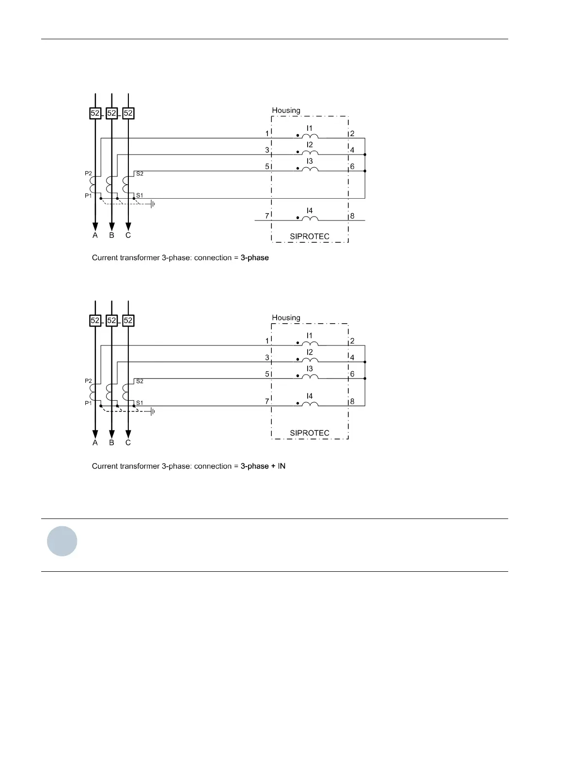
Figure A-5 Connection to a 3-Wire Current Transformer (Residual Current to be Calculated)
[tileite2-070211-01.tif, 3, en_US]
Figure A-6 Connection to a 3-Wire Current Transformer and Measured Zero-Sequence Current (Current in
Common Return Path)
i
i
NOTE
The switchover of current polarity at the 3-phase current transformer causes a rotation in the direction of
electric current for current input I4 (I
N
)!
A.4
Appendix
A.4 Connection Examples for Current Transformers
462 SIPROTEC 5, Fault Recorder, Manual
C53000-G5040-C018-5, Edition 11.2017

Table of Contents

Other manuals for Siemens SIPROTEC 5

Questions and Answers:

Question and Answer IconNeed help?

Do you have a question about the Siemens SIPROTEC 5 and is the answer not in the manual?

Siemens SIPROTEC 5 Specifications

General IconGeneral
SeriesSIPROTEC 5
Communication ProtocolsIEC 61850, DNP3, Modbus
CybersecurityRole-based access control, secure communication
Modular DesignYes
Hardware RedundancyOptional
Operating Temperature-25°C to +70°C
Digital InputsConfigurable, number depends on I/O modules
Digital OutputsConfigurable, number depends on I/O modules
Analog InputsConfigurable, number depends on I/O modules
Current Transformer InputsConfigurable, number depends on I/O modules
Voltage Transformer InputsConfigurable, number depends on I/O modules
Time SynchronizationIRIG-B, SNTP, PTP
Protection FunctionsOvercurrent, Differential, Distance, Over/Under Voltage, Frequency
Housing19-inch Rack Mount
DimensionsDepends on module configuration
WeightDepends on module configuration
Voltage Input24V DC, 48V DC, 110V DC, 125V DC, 220V DC, 250V DC

Related product manuals