•
Current trigger 1-phase (also see 7.5.2.1 Overview of Functions )
•
Current trigger 3-phase (also see 7.5.2.1 Overview of Functions )
•
Power trigger 1-phase (also see 7.4.4.1 Overview of Functions)
•
Power trigger 3-phase (also see 7.5.4.1 Overview of Functions)
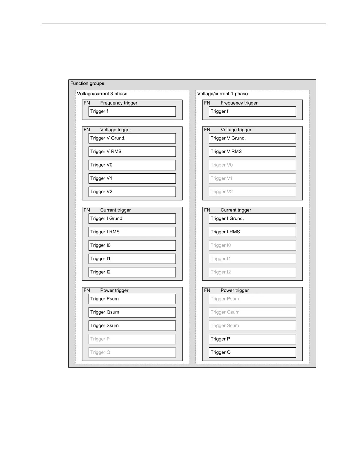
[dwfnreco-140313-01.tif, 2, en_US]
Figure 7-43
Structure of the Trigger Functions
Trigger Functions of the Analog Trigger
For a trigger detection, the trigger blocks compare the applied actual value (measured value) with the config-
ured trigger criteria (threshold values). The appropriate trigger starts a fault record in the fast-scan and/or
slow-scan recorder with the detection of a trigger criterion (exceeding or dropping below a set parameter
threshold value). The threshold values are checked on a half-period cycle for all measured values.
7.3.2.2
Fault Recorder
7.3 Function Description Analog and Binary Triggers
SIPROTEC 5, Fault Recorder, Manual 263
C53000-G5040-C018-5, Edition 11.2017

 Loading...


