[dw_powerswing_center, 1, en_US]
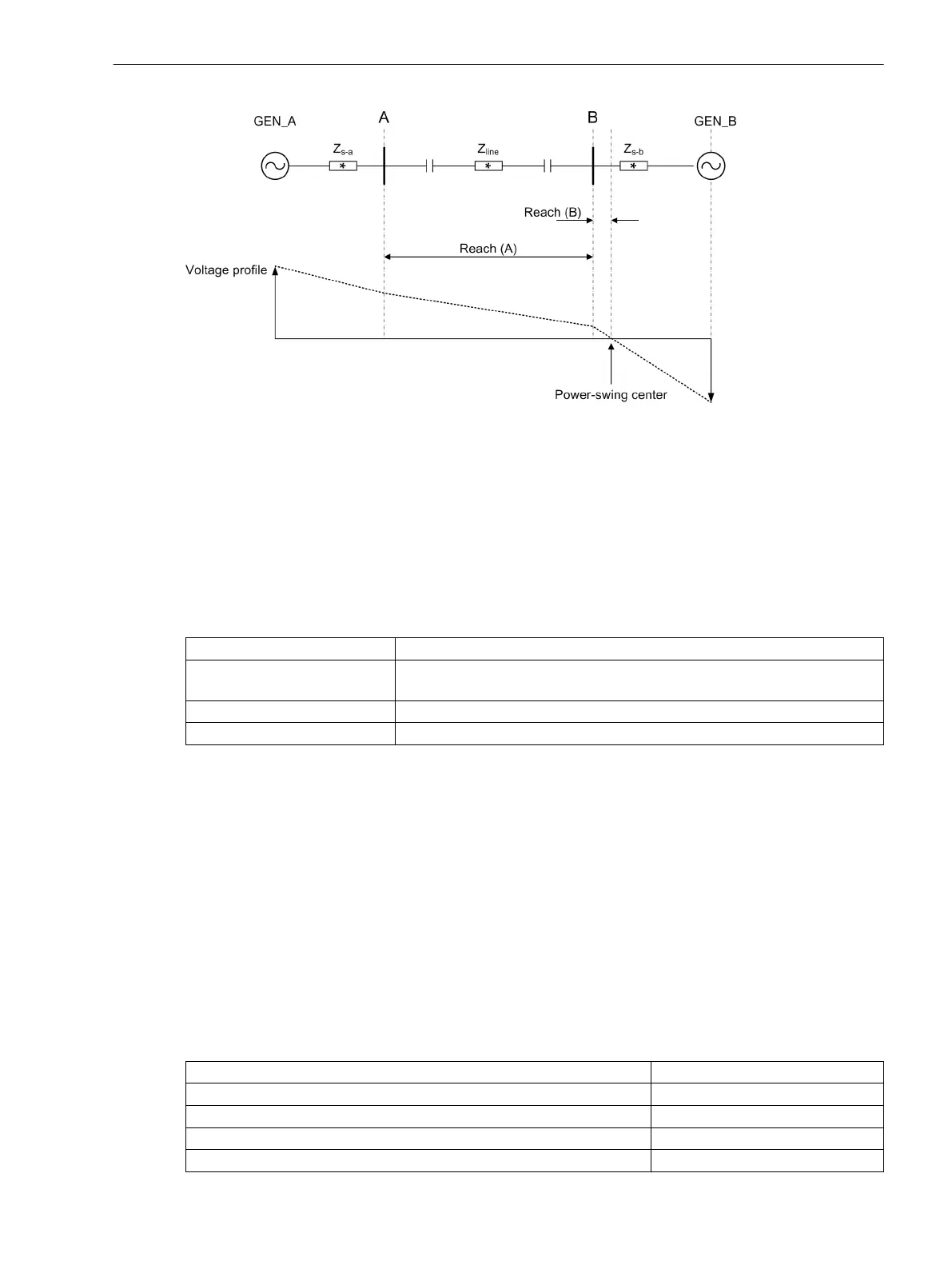
Figure 7-69 Power-Swing Center
Power-swing detection operates on a phase-segregated basis in the event of power-swing currents ≥ 10 % of
the rated current and power-swing frequencies between 0.1 Hz and 8 Hz.
Application and Setting Notes, Trigger Power Swing
Parameter: Mode
•
Default setting Mode = off
With the parameter Mode, you activate the trigger for normal operation (on) or the test mode (test).
Parameter Value
Description
on
The Trigger Psw # function block is activated and the power swing is moni-
tored according to the set trigger parameters.
off
The Trigger Psw # function block is deactivated.
test
The Trigger Psw # function block is activated for test purposes.
Parameters: X reach, R (ph-g), and R (ph-ph)
•
Default setting X reach = 100
•
Default setting R (ph-g) = 100
•
Default setting R (ph-ph) = 200
With the parameters X reach, R (ph-g), and R (ph-ph), you set the parameters of a power-swing
polygon within which power-swing-typical resistance changes cause triggering. Resistance changes outside
this polygon do not cause triggering. You can adapt the sensitivity of power-swing detection by changing the
default values (see the following calculation example).
Calculation Example:
If triggering occurs using the default settings even during non-critical power swings, for example, you can
adapt the sensitivity. This calculation example serves as orientation.
For a given line, the following data are known:
3-phase short-circuit current on the left line
20 kA/-72°
3-phase short-circuit current on the right line 12 kA/-83
Line impedance (5.17 + 19.31i) Ω
Primary rated voltage 110 kV
Primary rated current 800 A
7.5.4.8
Fault Recorder
7.5 Trigger Functions 3-Phase
SIPROTEC 5, Fault Recorder, Manual 343
C53000-G5040-C018-5, Edition 11.2017

 Loading...


