EasyManuals Logo

Siemens SIPROTEC 5 User Manual

Siemens SIPROTEC 5
490 pages
To Next Page IconTo Next Page
To Previous Page IconTo Previous Page
Page #183 background imageLoading...
Page #183 background image
Addr. Parameter C Setting Options Default Setting
_:13111:108 Channel 1:Resolution
1
0.1
0.01
0.001
0.1
_:13111:107 Channel 1:Range active
0
1
false
_:13111:104 Channel 1:Conversion
factor
1 to 1000000 100
_:13111:105 Channel 1:Upper limit 0.00 mA to 20.00 mA 20.00 mA
_:13111:109 Channel 1:Upper limit -
Sensor
-1000000 to 1000000 100
_:13111:106 Channel 1:Lower limit 0.00 mA to 20.00 mA 4.00 mA
_:13111:110 Channel 1:Lower limit -
Sensor
-1000000 to 1000000 100
Information List
No. Information Data Class
(Type)
Type
General
_:2311:53 General:Health ENS O
_:2311:56 General:Failure SPS O
Channel 1
_:13111:53 Channel 1:Health ENS O
_:13111:71 Channel 1:Failure SPS O
_:13111:301 Channel 1:20-mA output scale MV O
_:13111:302 Channel 1:20-mA output raw MV O
Communication with 20-mA Unit
Integration of a Serial 20-mA Unit
Connection of the Communication Lines
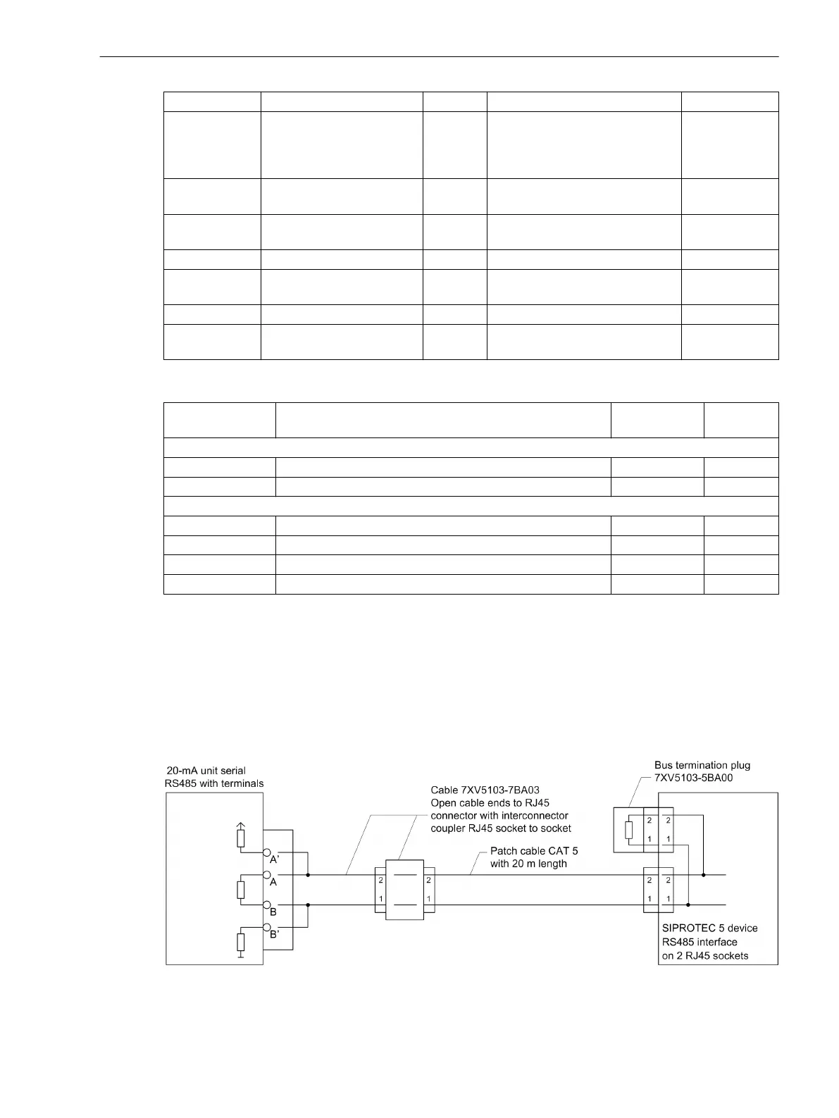
Figure 6-40 shows how to connect the 20-mA unit to the SIPROTEC 5 device. Note that Pin 1 of the RJ45 plug
is connected to RTD-B and Pin 2 is connected to RTD-A.
[dwve20au-150213-01.tif, 1, en_US]
Figure 6-40 Connection of the 20-mA Unit to the SIPROTEC 5 Device
6.5.4.4
6.5.5
6.5.5.1
Function-Group Types
6.5 Function-Group Type Analog Units
SIPROTEC 5, Fault Recorder, Manual 183
C53000-G5040-C018-5, Edition 11.2017

Table of Contents

Other manuals for Siemens SIPROTEC 5

Questions and Answers:

Question and Answer IconNeed help?

Do you have a question about the Siemens SIPROTEC 5 and is the answer not in the manual?

Siemens SIPROTEC 5 Specifications

General IconGeneral
SeriesSIPROTEC 5
Communication ProtocolsIEC 61850, DNP3, Modbus
CybersecurityRole-based access control, secure communication
Modular DesignYes
Hardware RedundancyOptional
Operating Temperature-25°C to +70°C
Digital InputsConfigurable, number depends on I/O modules
Digital OutputsConfigurable, number depends on I/O modules
Analog InputsConfigurable, number depends on I/O modules
Current Transformer InputsConfigurable, number depends on I/O modules
Voltage Transformer InputsConfigurable, number depends on I/O modules
Time SynchronizationIRIG-B, SNTP, PTP
Protection FunctionsOvercurrent, Differential, Distance, Over/Under Voltage, Frequency
Housing19-inch Rack Mount
DimensionsDepends on module configuration
WeightDepends on module configuration
Voltage Input24V DC, 48V DC, 110V DC, 125V DC, 220V DC, 250V DC

Related product manuals