[scpmubif-210415, 1, en_US]
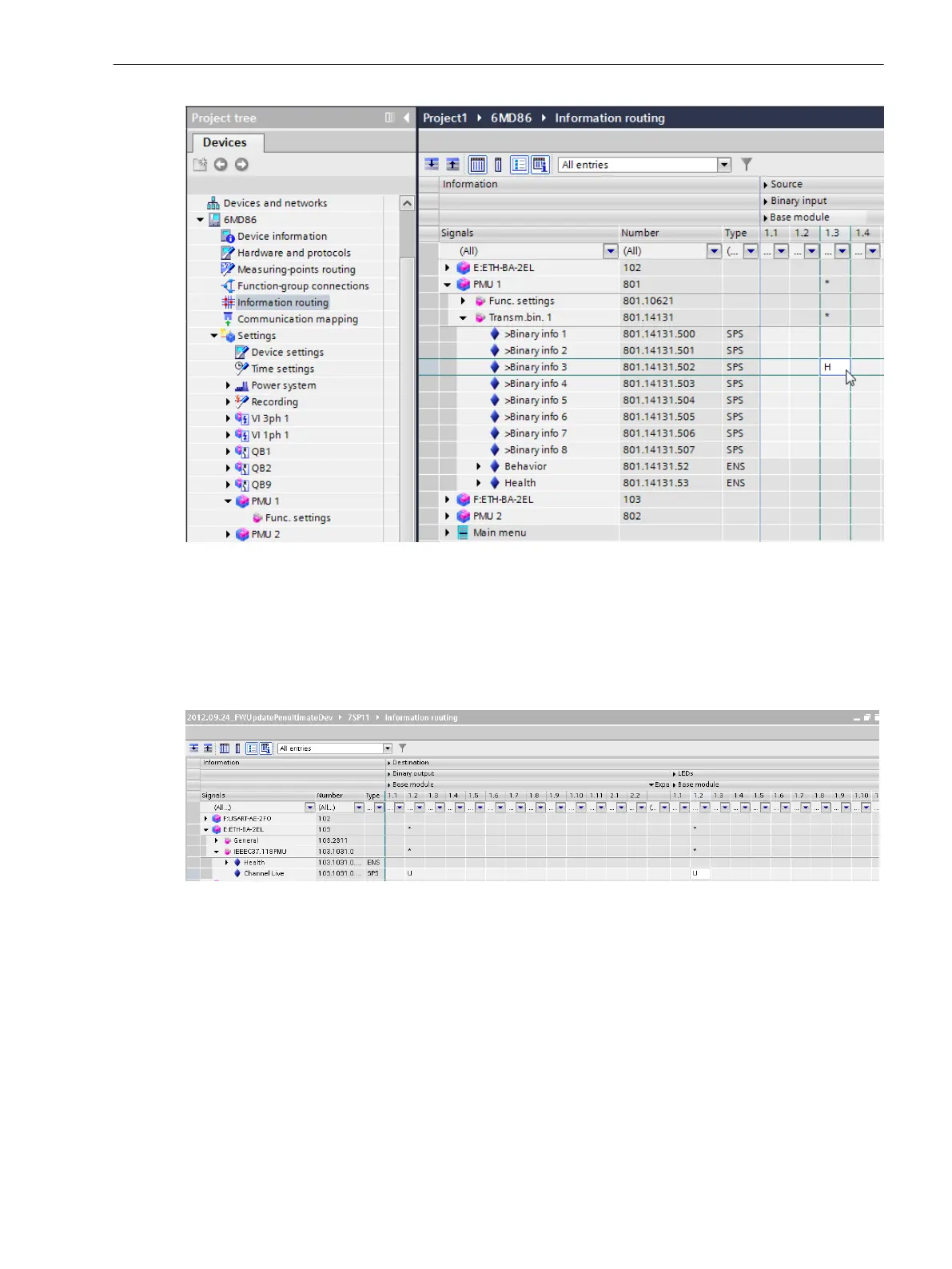
Figure 6-26
Information Routing in DIGSI 5
Routing Indications
The routable indication
ChannelLive
of the PMU log
•
raises when the PMU is connected to the PDC
•
clears when the connection to the PDC is interrupted.
[scparami-260912-01.tif, 1, en_US]
Figure 6-27 Log Indication for Display of the PMU/PDC Connection
Parameterizing the PMU on the Device
You can also change the PMU settings directly on the device. To do this, select the desired PMU instance on
the device display. By selecting menu item Settings you then access the editable setting values (see
Figure 6-28). Note that the parameter Port cannot be changed, because this corresponds to the physical slot
position of the communication module in question.
6.4.7
Function-Group Types
6.4 Function-Group Type Phasor Measurement Unit (PMU)
SIPROTEC 5, Fault Recorder, Manual 167
C53000-G5040-C018-5, Edition 11.2017

 Loading...


