[dwfncurr-161012-01.tif, 1, en_US]
Figure 7-63 Structure/Embedding of the 3-Phase Voltage/Current Function
A maximum of 3 function blocks of the same type can be entered or removed within the function. For unam-
biguous differentiation the function blocks automatically receive a sequential number in the name of the func-
tion block, for example, Trig I RMS 1, Trig I RMS 2, and Trig I RMS 3.
Each function block contains the level trigger Max. trigger and Min. trigger, as well as the gradient
trigger dM/dt rise (/Filter time) and dM/dt drop active of the corresponding measurand.
Function Description
Logic
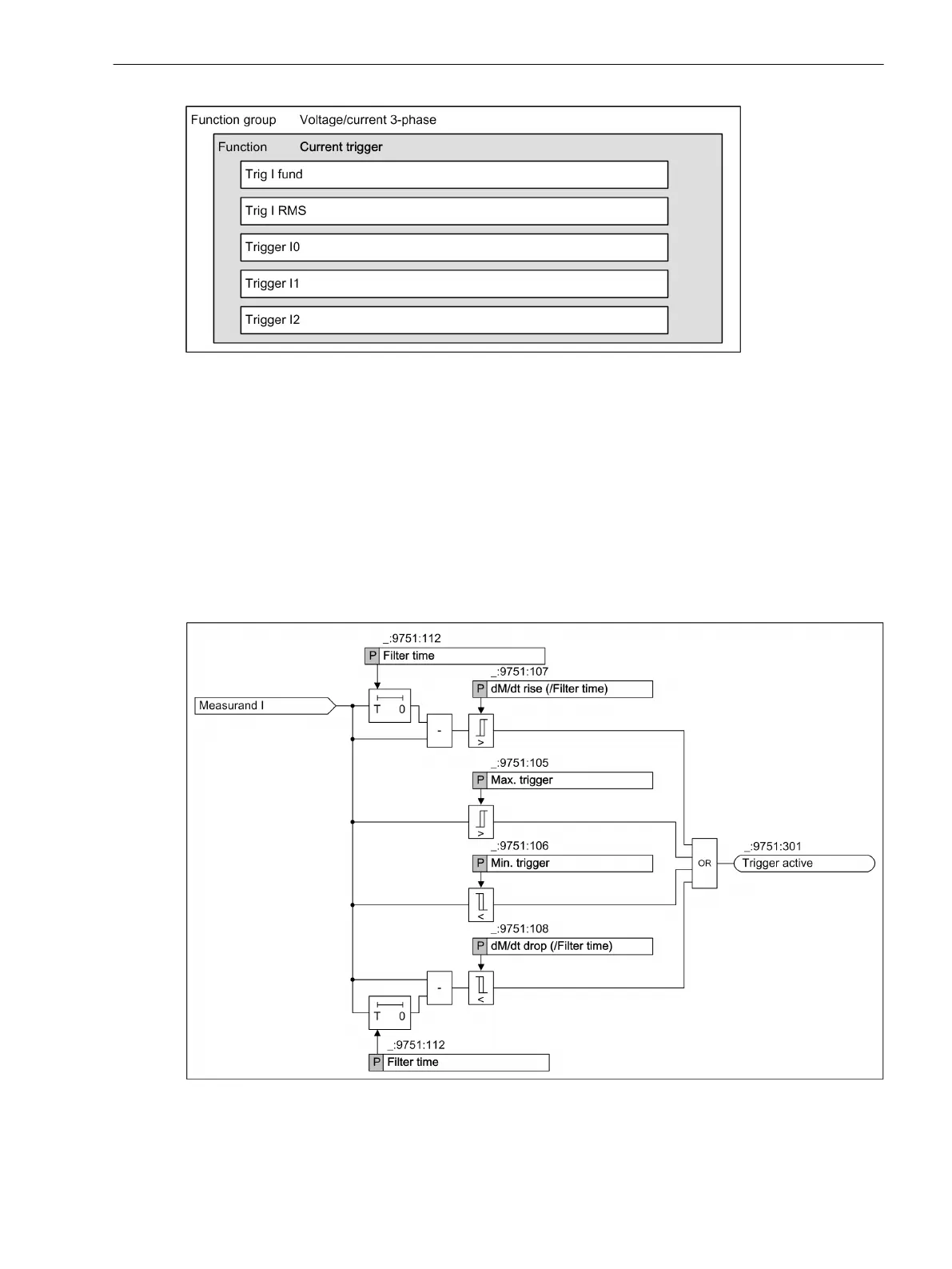
The following logic diagram shows the operating state of the current trigger.
[dwlotrii-161012-01.tif, 1, en_US]
Figure 7-64
Logic Diagrams of the Current Trigger
The function Current trigger is subdivided into Level and Gradient trigger.
7.5.2.3
Fault Recorder
7.5 Trigger Functions 3-Phase
SIPROTEC 5, Fault Recorder, Manual 313
C53000-G5040-C018-5, Edition 11.2017

 Loading...


