Operational Measured Values
Operational measured values are assigned to different function groups.
The values can be displayed as primary and secondary values and as percentage values.
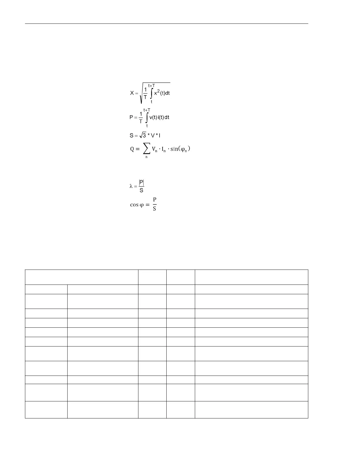
The operational measured values are calculated according to the following definition equations:
RMS values
Active power
Apparent power
Reactive power
n
φ
n
Harmonic order
The angle difference between the voltage and current of the nth harmonic
Power factor
Active power factor
Operational Measured Values of the Function Groups
The following table describes the operational measured values of the Voltage, 3-phase and Voltage/current
3-phase function groups.
All recorder functions have access to the values.
Table 9-1
Operational Measured Values of the Voltage/Current 3-Phase Function Group
Measured Values Primary Secon-
dary
% Referenced to
I
A
, I
B
, I
C
Phase currents A A Rated operating current of the primary values
3I
0
Calculated zero-sequence
current
A A Rated operating current of the primary values
I
N
Neutral-point phase current A A Rated operating current of the primary values
I
NS
Sensitive ground current A mA Rated operating current of the primary values
V
A
, V
B
, V
C
Phase-to-ground voltages kV V Rated operating voltage of primary values/√3
V
AB
, V
BC
, V
CA
Phase-to-phase voltage kV V Rated operating voltage of the primary values
V
0
Calculated zero-sequence
voltage
kV V Rated operating voltage of primary values/√3
V
N
Measured neutral-point
displacement voltage
kV V Rated operating voltage of primary values/√3
f Frequency Hz Hz Rated frequency
P Active power
(total power)
MW W Active power of the primary values
√3 · V
rated
· I
rated
Q Reactive power
(total power)
Mvar var Reactive power of the primary values
√3 · V
rated
· I
rated
9.3
Measured and Energy Values
9.3 Operational Measured Values
414 SIPROTEC 5, Fault Recorder, Manual
C53000-G5040-C018-5, Edition 11.2017

 Loading...


