required. It can be necessary to connect additional measuring points to the function group, depending on the
nature of the user functions used. The configuration is done via the Function group connections editor in
DIGSI 5.
You can find more detailed information on this in chapter 2.1 Function Embedding in the Device.
The function groups 3-phase voltage, Voltage/current 1-phase, and Voltage/current 3-phase have the
following interfaces to the measuring points:
•
3-phase voltage
The measurands from the 3-phase voltage system are supplied via this interface. Depending on the
connection type of the transformers, in the 3-phase voltage system these are, for example, V
A
, V
B
, V
C
.
•
Voltage/current 1-phase and Voltage/current 3-phase
The measurands from the 1-phase or the 3-phase voltage and current system are supplied via these inter-
faces. All values that can be calculated from the measurands are also provided via these interfaces.
•
Phasor Measurement Unit (PMU)
The measurands from the PMU are supplied via this interface.
Power-System Data and Function Groups and Functions that cannot be Configured
The power-system data and the PMU function group are visible, but cannot be changed.
Function Description
Input and Output Signals
Recordings are started on the fast-scan and slow-scan recorders if a trigger criterion is satisfied or a control
input is activated.
The fault recorder makes different input signals available, with which recordings can be specifically started
and deleted. The output signals provide information about the function status.
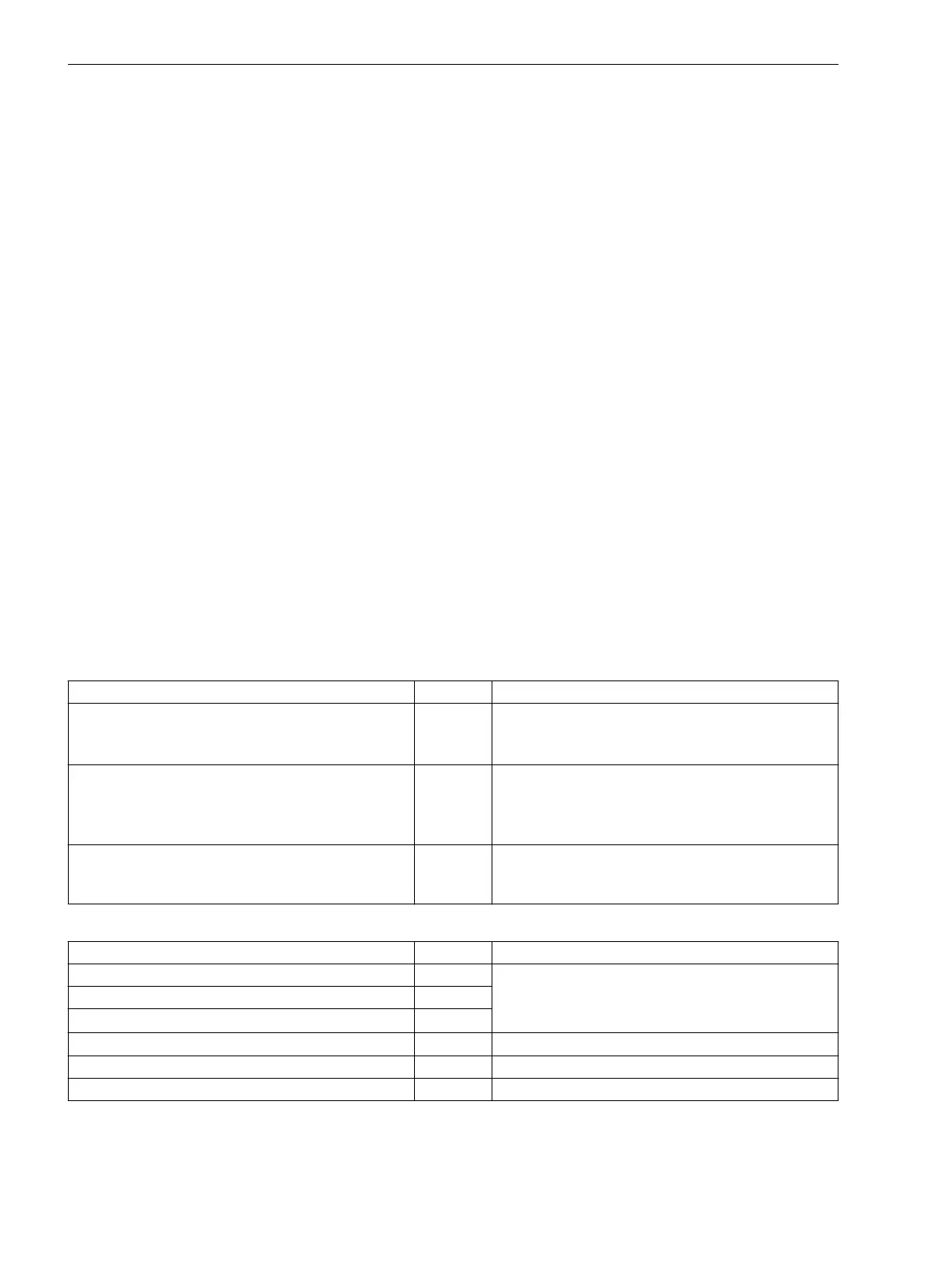
In the following table you can find input signals of the fault-recording functions:
Name
Type Description
Control:
Start record
SPC Start of a recording preferably via IEC 61850
The set pre and post-trigger time are taken into
account.
Control:
>External start
SPS Start of a recording preferably via a binary input or a
logic block chart.
The set pre and post-trigger time are taken into
account.
Control:
>Manual start
SPS Start of a recording with fixed time (Manual
record time parameter), preferably using a func-
tion key
In the following table you can find output signals of the fault-recording functions:
Name
Type Description
General:
Mode (controllable)
ENC Status feedback of the fault recording according to
Chapter 2.3 Function Control
General:
Behavior
ENS
General:
Health
ENS
Control:
Fault number
INS Indication of the error number for current fault
Control:
Recording started
SPS Fault recording running
Control:
Record made
SPS End of recording
7.2.3
Fault Recorder
7.2 Function-Group Type Recorder
232 SIPROTEC 5, Fault Recorder, Manual
C53000-G5040-C018-5, Edition 11.2017

 Loading...


