Configuration of Stored Indications with DIGSI 5
•
In the Information routing of each device set up in DIGSI 5, you can route binary signals to LEDs and
output contacts. For this open in the project tree.
Project → Device → Information Routing
•
Click with the right mouse button on the routing field of your binary indication in the desired LED or
binary output column in the routing range of the targets.
You are offered the following options:
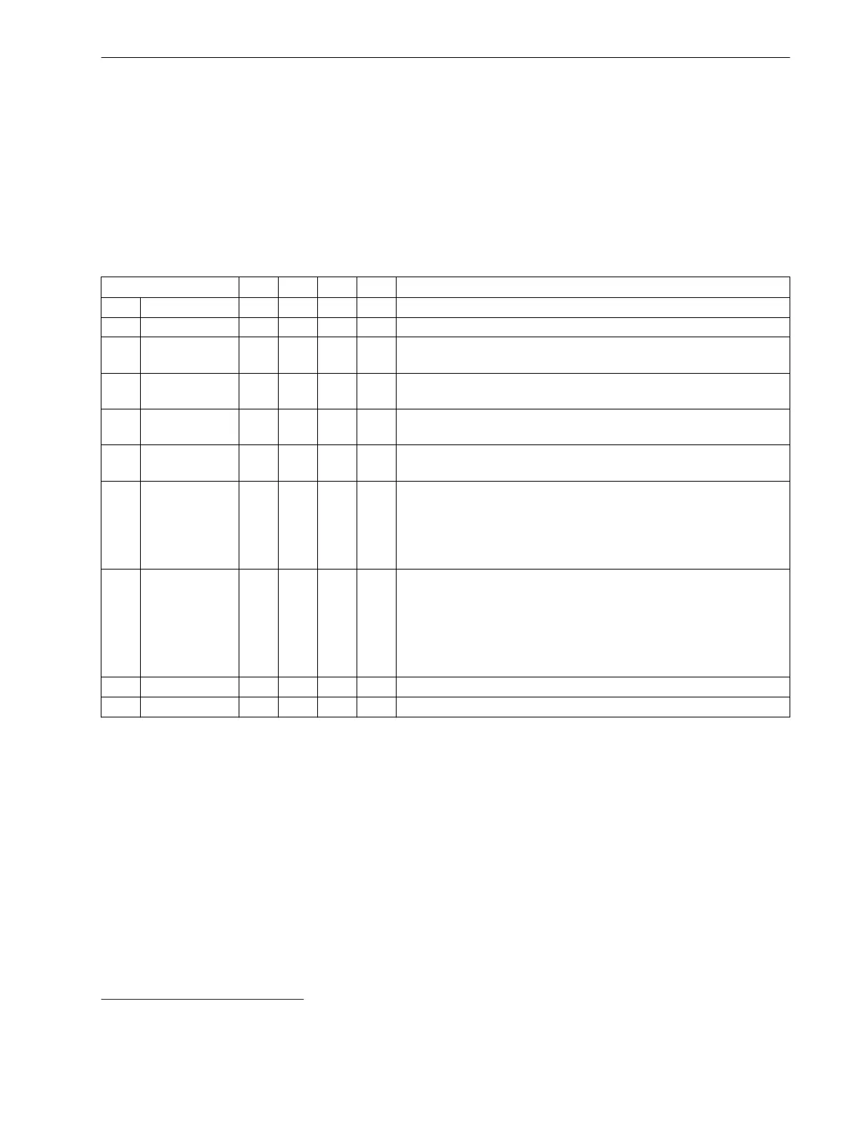
Table 7-4 Overview of Routing Options
Routing Options LED
BI
10
BO
11
FK
12
Description
(unrouted) X X X X The signal is not routed.
X (routed) X The signal is routed.
H Active with
voltage
X There is a voltage applied at the routed binary input
L Active without
voltage
X X There is no voltage applied at the routed binary input
V Unlatched X X The signal is routed as unsaved. Activation and reset of the output
(LED, BO) occurs automatically via the binary-signal value.
G Latched X X The binary signal is latched when the output (LED, binary output) is
activated. To reset, a targeted confirmation must occur.
V Toggle X With this routing option, the trigger rises with the first operational
handling (LED on). When the function key is activated again, the
trigger clears (LED off).
This setting applies for the controllable
Start record
and binary
inputs
>External start
and
>Manual start
.
P (Trigger pulse) X With this routing option, the trigger rises and clears. The LED display
illuminates approx. 200 ms.
This setting applies for the binary inputs
>External start
and
>Manual start
.
This routing option is practical for a routing of the function key to
>Manual start
.
On On X
This setting applies only for the controllable
Start record
.
Off Off X
This setting applies only for the controllable
Start record
.
10
Binary input
11
Binary output
12
Function key
Fault Recorder
7.2 Function-Group Type Recorder
SIPROTEC 5, Fault Recorder, Manual 233
C53000-G5040-C018-5, Edition 11.2017

 Loading...


