You can find the detailed description, in table form, of the fault responses at the end of chapter 8. You will
find corresponding corrective measures there.
Device Operating Hours
The
Device operating hours
statistical value counts the operating hours of the physical device. The
starting time and the time in Fallback mode are not considered.
You can neither reset nor change the statistical value.
Analog-Channel Supervision via Fast Current-Sum
Overview of Functions
The function Supervision of the device-internal analog-digital converters it performs the following tasks:
•
Supervision of the correct functioning of the device-internal analog-digital converters, based on the sum
of all currents of one measuring point in the secondary circuit.
•
Detection of failures in the device-internal measuring circuits (for example, analog-digital converter)
•
Blocking of protection and control functions that process the measured values from this current meas-
uring point (for example, differential protection). This avoids an overfunction of the device.
The supervision principle is based on fast current sum supervision with connection of the neutral-point current
to the 4th current measurement input. In order to ensure that even the fast tripping stages of the protection
functions can be blocked in time before a spurious pickup, the fast current measurement is based on instanta-
neous values.
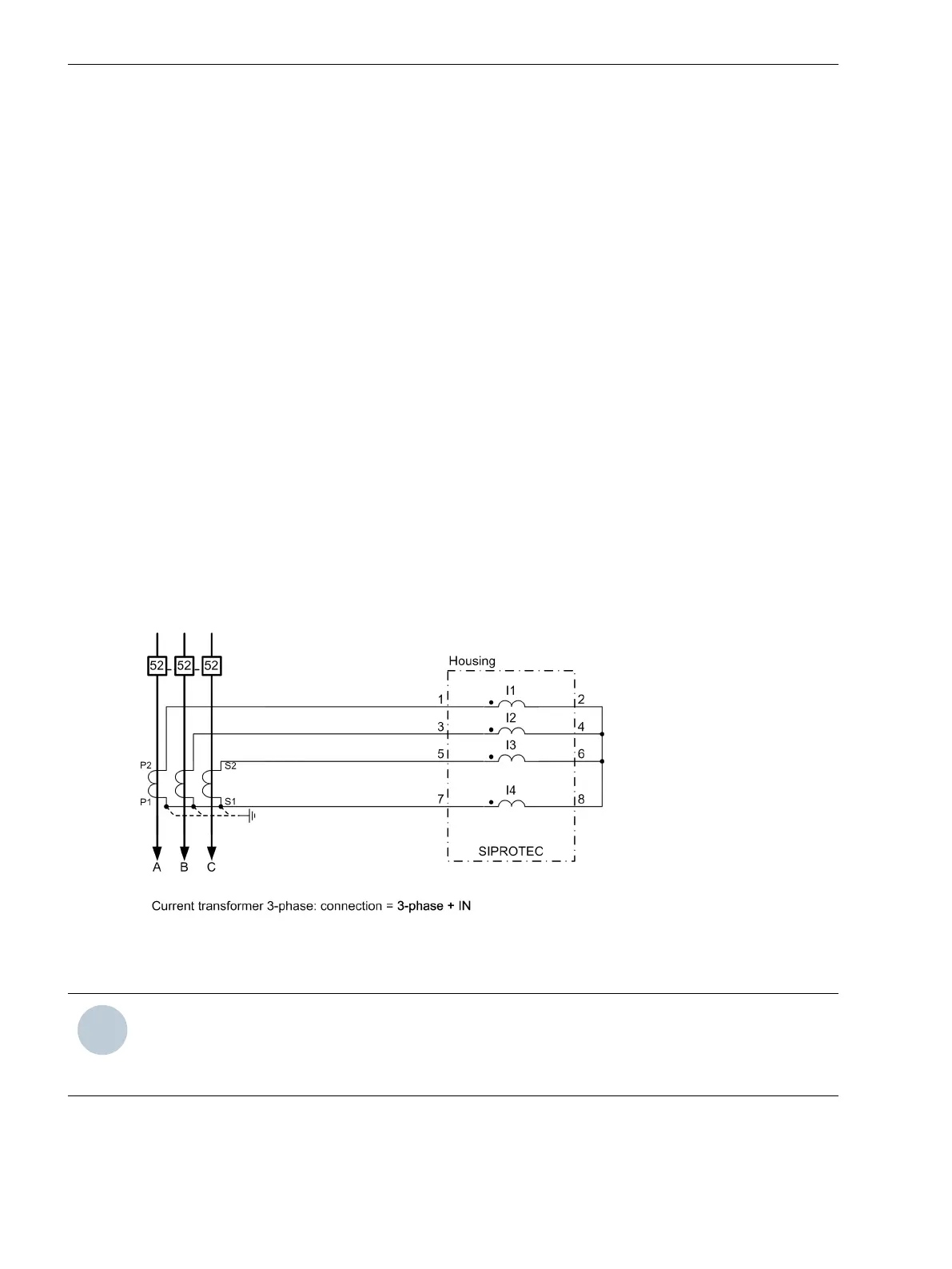
For Analog-digital converter supervision, the neutral-point current of the line to be protected must be
connected to the 4th current measuring input (I
N
). The 4th current measuring input must be routed via the
current-transformer neutral point (I
N
neutral point) (see next figure).
[tileite2-070211-01.tif, 3, en_US]
Figure 8-23 Connection to a 3-Phase Current Transformer and Measured Zero-Sequence Current (Current
in Common Return Path)
NOTE
The analog channel supervision via fast current sum is only available when the 4th current input is a
protection-class current transformer. In the DIGSI 5 project tree, under Device → Measuring-point
routing, set the connection type 3-phase + IN for the current measuring point.
8.4.2
8.4.2.1
Supervision Functions
8.4 Supervision of the Device Hardware
394 SIPROTEC 5, Fault Recorder, Manual
C53000-G5040-C018-5, Edition 11.2017

 Loading...


