[sctrigge-280113-01.tif, 1, en_US]
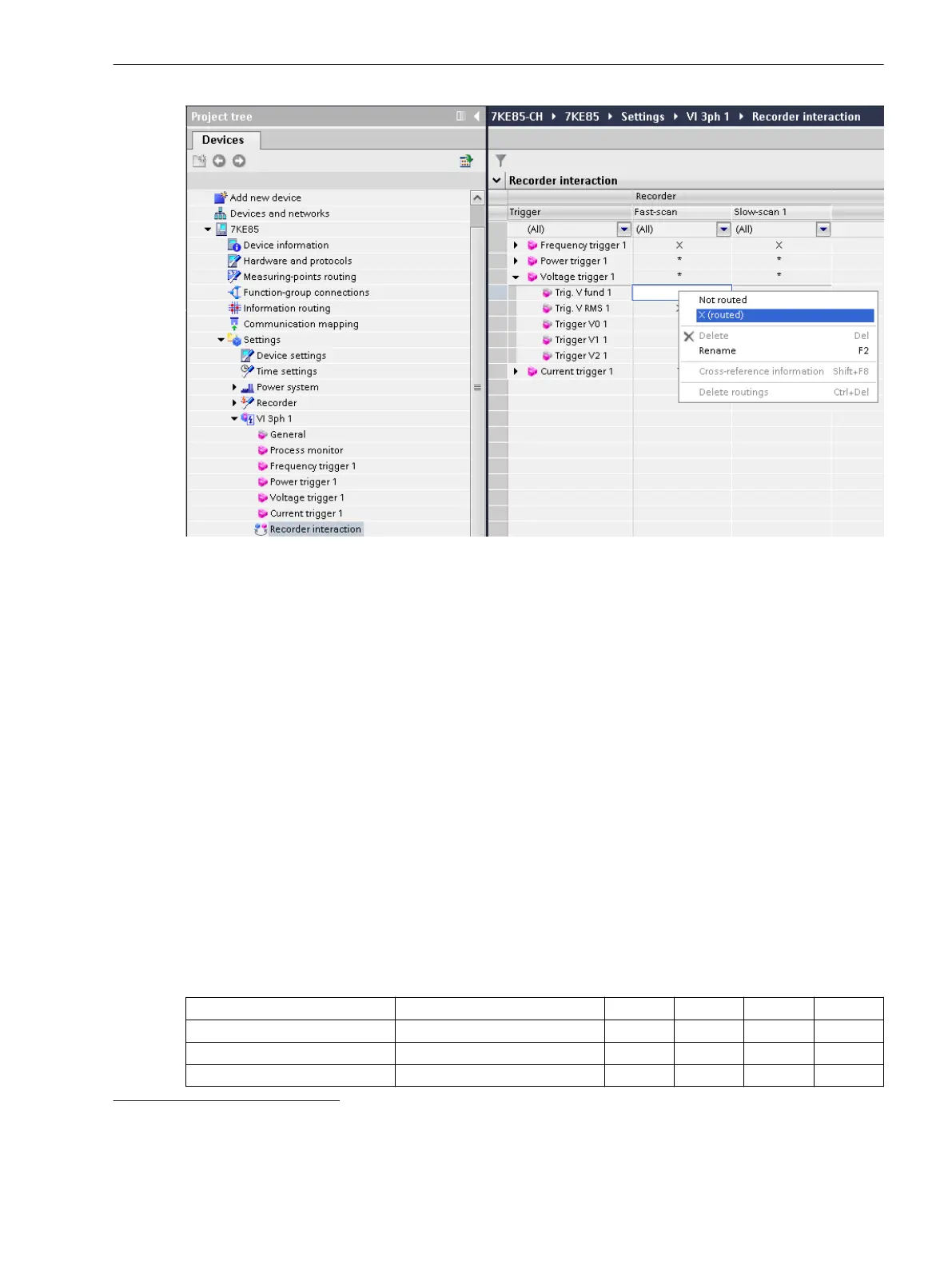
Figure 7-13
Trigger Routing in the Recorder Interaction Matrix
Routing the Signals and Indications in the Information Routing
You can find a detailed description of the routings in chapter 7.2.3 Function Description.
²
Rout signals, indications, etc. with the Information routing to sources and goals.
The Information routing is a device-oriented tool. A separate Information routing is available for each
offline configuration present in a project.
Routing the Measured Values in the Information Routing
²
You can find more information about the measured values that can be routed as well as recommenda-
tions in chapter 7.6.1.2 Using Measurands .
Step 3: Evaluating Recordings
Generating the Record by the Device
The records generated by the fault recorder can be loaded and converted by DIGSI 5 or SICAM PQS. A
maximum of 3 communication connections are possible, irrespective of the type of DIGSI 5 or IEC 61850.
Depending on the recorder, the records are provided in different file formats (see the following table).
Table 7-2
File Formats Used by the Individual Recorders
Interface File Format
FSR
6
SSR
7
CR
8
TR
9
DIGSI 5 SIPROTEC 5 X X X X
IEC 61850 SIPROTEC 5 X X
IEC 61850 COMTRADE X X
7.1.4
6
FSR: Fast-Scan Recorder
7
SSR: Slow-Scan Recorder
8
CR: Continuous recorder
9
TR: Trend recorder
Fault Recorder
7.1 Introduction to DIGSI 5
SIPROTEC 5, Fault Recorder, Manual 225
C53000-G5040-C018-5, Edition 11.2017

 Loading...


