NOTE
The Mode of the individual recorder depends on the settings of the parameter Mode in the higher-level
function General.
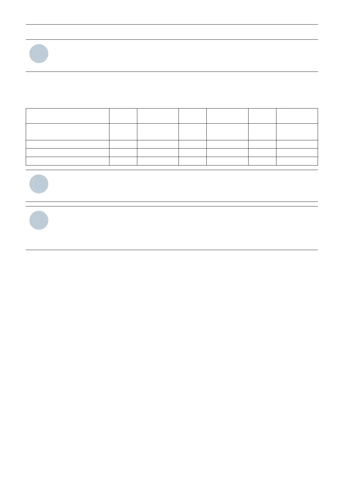
The status of the function resulting from the parameter Mode and the superordinate state of the recorder is
shown in the following table.
Table 7-1 Resulting State of the Function (from Connection of Parameter Mode and Superordinate State)
Mode State of the
Recorder
Mode State of the
Recorder
Mode State of the
Recorder
General Function
(Superordinate State)
On Off Test
Individual recorder On On On Off On Test
Individual recorder Off Off Off Off Off Off
Individual recorder Test Test Test Off Test Test
NOTE
Every change of a recorder parameter (with the exception of changing the mode and trigger parameters)
results in a restart of the device.
NOTE
A currently existing trigger violation does not trigger fault records if
•
the device is restarted
•
the device, the recording, or the mode of the recorder is switched from on to off.
Configuring Trigger Routing
You can route triggers to recorder instances. A trigger can be routed to one or more recorder instances. To
generate a fault record, assign the triggers to the recorders.
²
Double-click Recorder interaction in the project tree in DIGSI 5.
²
Right-click X (routed).
Fault Recorder
7.1 Introduction to DIGSI 5
224 SIPROTEC 5, Fault Recorder, Manual
C53000-G5040-C018-5, Edition 11.2017

 Loading...


