NOTE
•
The logged indications are preconfigured and cannot be changed!
•
This log, which is organized as a ring buffer. cannot be deleted by the user!
•
If you want to archive security-relevant information from the device without loss of information, you
must regularly read this log.
Device-Diagnosis Log
The logging and the display of concrete instructions are done in the device-diagnosis log during
•
required maintenance (e.g. battery supervision)
•
identified hardware defects
•
compatibility problems
Up to 500 indications can be stored in the device-diagnosis log. In normal operation of the device, it is suffi-
cient for diagnostic purposes to follow the entries of the operational log. This specific significance is assumed
by the device-diagnosis log when the device is no longer ready for operation due to hardware defect or
compatibility problems and the fallback system is active.
Reading from the PC with DIGSI 5 in Normal Operation
•
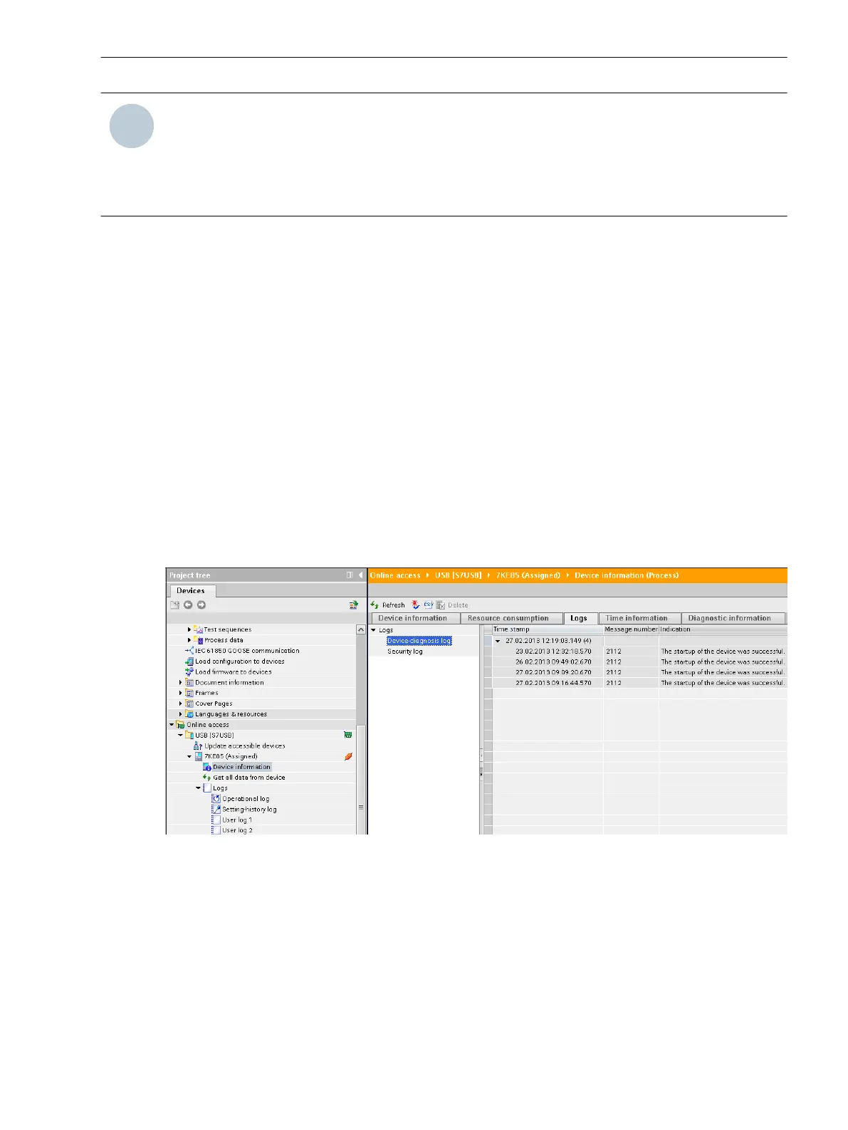
To reach the device-diagnosis log of your SIPROTEC 5 device, use the project tree window.
Project → Device → Device Information → Logs → Device-diagnosis log
The device-diagnosis log is shown to you in the state last loaded from the device.
•
To update (synchronization with the device) click the button Update in the headline of the indication list.
[scgerdia-220213-01.tif, 1, en_US]
Figure 3-17 Reading the Device-diagnosis Log with DIGSI 5
Reading on the Device through the On-Site Operation Panel in Normal Operation
•
To reach the diagnosis log from the main menu, use the navigation keys of the on-site operation panel.
Main Menu → Test & Diagnosis → Indications → Device diagnosis
•
You can navigate on the on-site operation panel using the navigation keys (top/bottom) inside the
displayed indication list.
3.1.9
System Functions
3.1 Indications
SIPROTEC 5, Fault Recorder, Manual 59
C53000-G5040-C018-5, Edition 11.2017

 Loading...


