Configurability
The indication capacity of the log is configured in a specifically defined column of the information routing
(matrix) of DIGSI 5:
Target → Log → Column Sequence of events
The indication General > Behavior is pre-routed in the selected application templates and functions from the
library.
Setting-History Log
All individual parameter changes and the downloaded files of entire parameter sets are recorded in the log for
parameter changes. This clarifies whether completed parameter changes are connected to logged events (e.g.
faults). On the other hand, it is possible to prove with fault analyses, for example, that the current status of all
settings actually corresponds to that of the time of the fault. Up to 200 indications can be stored in the
setting-history log.
Reading from the PC with DIGSI 5
•
To reach the log for parameter changes of your SIPROTEC 5 device, use the project tree window.
Project → Device → Process Data → Log → Setting-history log
The setting-history log is shown to you in the state last loaded from the device.
•
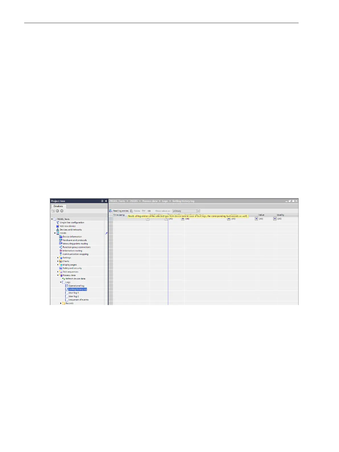
To update (synchronization with the device), click the button Read log entries in the headline of the
indication list (see the following figure).
[scparmel-220213-01.tif, 1, en_US]
Figure 3-11 Reading the Setting-history Log with DIGSI 5
Reading on the Device through the On-Site Operation Panel
•
To reach the setting-history log from the main menu, use the navigation keys of the on-site operation
panel.
Menu → Indications → Setting-history log
•
You can navigate on the on-site operation panel using the navigation keys (top/bottom) inside the
displayed indication list.
3.1.6
System Functions
3.1 Indications
54 SIPROTEC 5, Fault Recorder, Manual
C53000-G5040-C018-5, Edition 11.2017

 Loading...


