[scparhmi-220213-01.tif, 1, en_US]
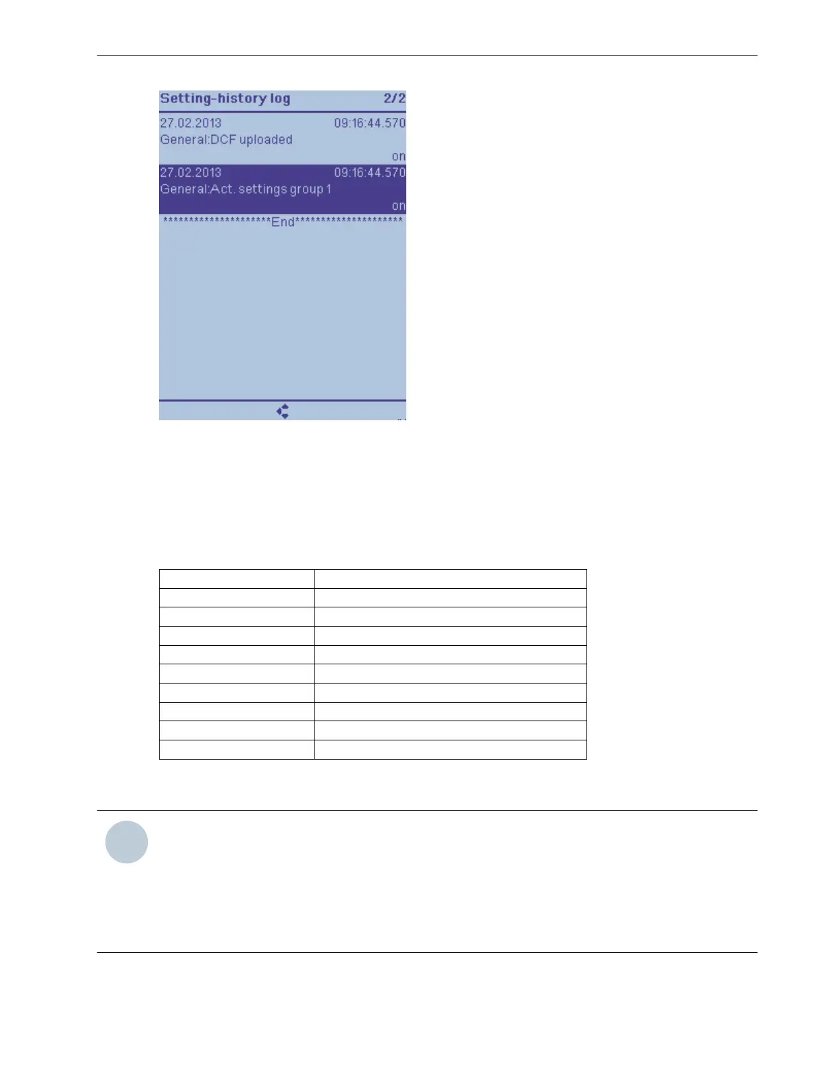
Figure 3-12 Reading the Setting-history Log on the On-Site Operation Panel of the Device
Indication Categories in the Setting-History Log
For this log, there is selected information that is stored in case of successful as well as unsuccessful parameter
changes. The following list gives you an overview of this information.
Table 3-3
Overview of indication types
Displayed Information Explanation
Selection editing+ Selection of settings group to be edited
Reject+ Rejection of all changes successful
PG activation+ PG activation through command successful
PG activation- PG activation through command failed
set+ Parameter value was changed
Acceptance+ Acceptance of change successful
Acceptance- Acceptance of change failed
DCF loaded DCF loaded into device
PG 1 Settings group 1
For this log, there is selected information that is stored in case of successful as well as unsuccessful parameter
changes.
NOTE
•
The logged indications are preconfigured and cannot be changed!
•
This log, which is organized as a ring buffer, cannot be deleted by the user!
•
If you want to archive security-relevant information from the device without loss of information, you
must regularly read this log.
•
In the setting-history log you cannot route additional indication objects.
System Functions
3.1 Indications
SIPROTEC 5, Fault Recorder, Manual 55
C53000-G5040-C018-5, Edition 11.2017

 Loading...


