[scquitti-260213-01.tif, 1, en_US]
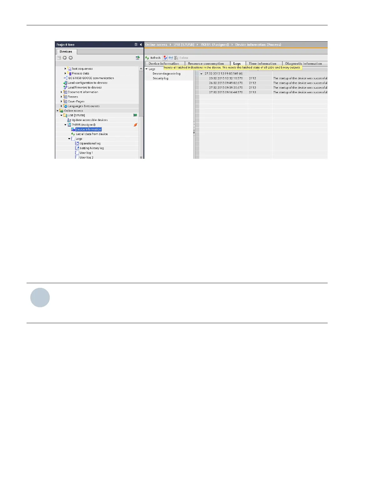
Figure 3-21 LED Reset via DIGSI 5
•
Click the Log tab.
•
Click the LED reset button (see the yellow line in the figure).
•
Enter the confirmation ID.
•
Confirm the process with OK.
Stored LEDs, output contacts and spontaneous fault messages are reset on the assigned device.
Confirmation of Stored Indications via a Protocol
Initiation of acknowledgment of stored indications can also occur through communication via a connected
substation automation technology. This can occur in conformance to standards (IEC 61850, IEC 60870-5-103)
or via configuration (mapping) of the LED reset input signal for any protocol. Stored LEDs, output contacts,
and spontaneous fault displays (display) are reset.
NOTE
The confirmation of stored indications then leads to the resetting of configured LEDs and output contacts,
as long as these active unstored indications are present in parallel. I.e., indications configured as unstored
are not affected by the confirmation process.
Test Mode and Influence of Indications on Substation Automation Technology
If the test mode of the device or of individual functions is switched on, the SIPROTEC 5 device marks indica-
tions sent to substation automation technology station control system with an additional test bit. This test bit
makes it possible to determine that an indication was set during a test. Necessary reactions in normal opera-
tion on the basis of an indication can thus be suppressed.
3.1.12
System Functions
3.1 Indications
64 SIPROTEC 5, Fault Recorder, Manual
C53000-G5040-C018-5, Edition 11.2017

 Loading...


