Delay failure indication
If it falls below the balance factor Threshold min/max and at the same time the maximum phase-to-phase
voltage exceeds the Release threshold, the delay of the failure indication begins, (parameter: Delay
failure indication). If both conditions persist during this time, the indication Failure is generated.
Blocking the Function
The following blockings reset the picked up function completely:
•
Externally or internally via the binary input signal
>Block function
•
A protection pickup
The pickup signal of a protection function blocks the
Failure
indication.
Application and Setting Notes
Parameter: Threshold min/max
•
Recommended setting value (_:102) Threshold min/max = 0.75
The Threshold min/max parameter is used to set the ratio between the minimum (V
min
) and the maximum
(V
max
) phase-to-phase voltage. Siemens recommends using the default setting.
Parameter: Release threshold
•
Recommended setting value (_:101) Release threshold = 50 V
With the Release threshold parameter you set the lower limit of the maximum phase-to-phase voltage
(V
max
). Siemens recommends using the default setting.
Parameter: Delay failure indication
•
Recommended setting value (_:6) Delay failure indication = 5.00 s
Set the Delay failure indication parameter so that overfunctions due to disturbing influences (such as
switching operations) are avoided. Siemens recommends using the default setting.
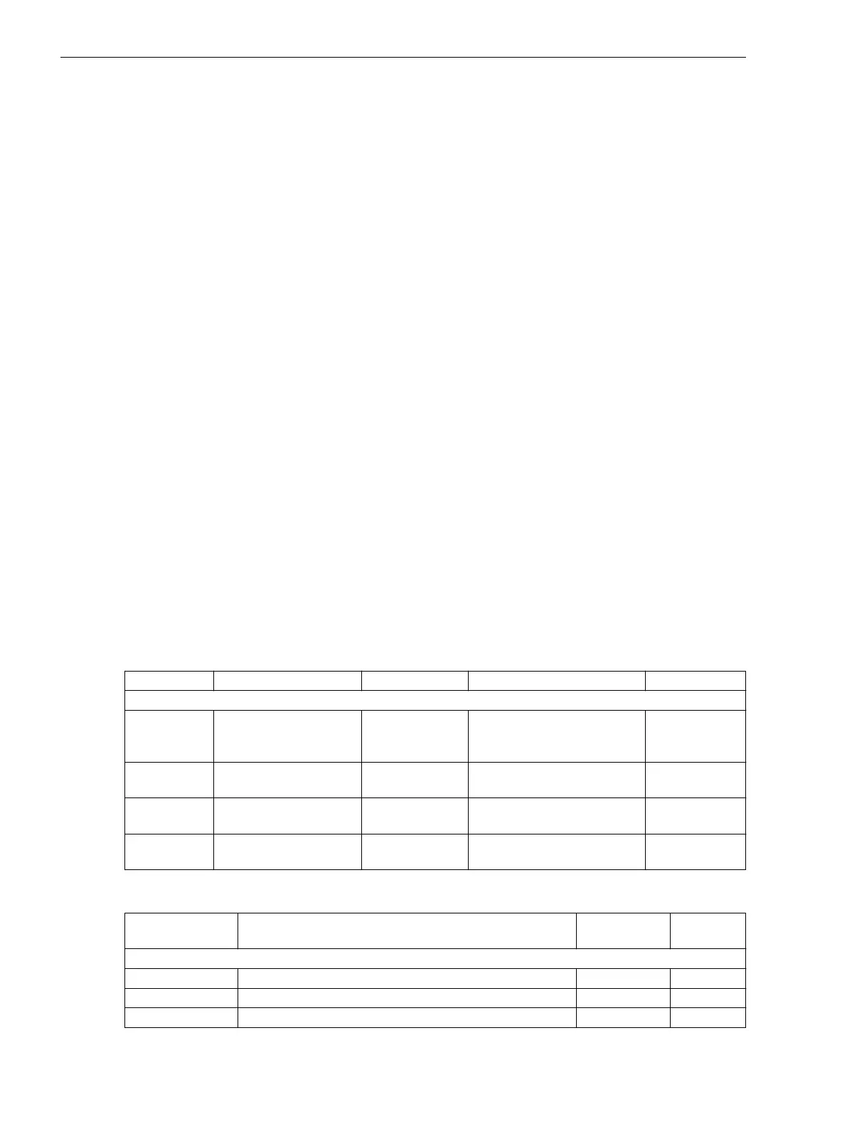
Settings
Addr.
Parameter C Setting Options Default Setting
Supv. balan. V
_:1 Supv. balan. V:Mode
•
off
•
on
•
test
off
_:101 Supv. balan. V:Release
threshold
0.300 V to 170.000 V 50.000 V
_:102 Supv. balan. V:Threshold
min/max
0.58 to 0.95 0.75
_:6 Supv. balan. V:Delay
failure indication
0.00 sto 100.00 s 5.00 s
Information List
No.
Information Data Class
(Type)
Type
Supv. balan. V
_:82 Supv. balan. V:>Block function SPS I
_:54 Supv. balan. V:Inactive SPS O
_:52 Supv. balan. V:Behavior ENS O
8.3.2.4
8.3.2.5
8.3.2.6
Supervision Functions
8.3 Supervision of the Secondary System
374 SIPROTEC 5, Fault Recorder, Manual
C53000-G5040-C018-5, Edition 11.2017

 Loading...


