EasyManuals Logo

Siemens SIPROTEC 5 User Manual

Siemens SIPROTEC 5
490 pages
To Next Page IconTo Next Page
To Previous Page IconTo Previous Page
Page #184 background imageLoading...
Page #184 background image
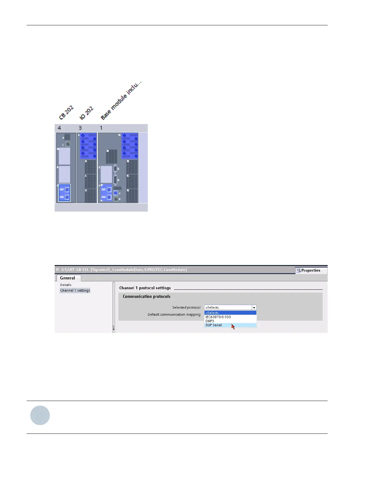
Adding a USART Module
Add a USART-AB-1EL or a USART-AC-2EL USART module in DIGSI to the device. The USART module must be
inserted at one of the plug-in positions for communication modules in the base module or in the CB202
expansion module (refer to the following figure).
[sc20ser3-220114-01-DE, 1, en_US]
Figure 6-41 Insertion Position for a USART Module
Selecting the SUP Protocol
Select the Slave Unit Protocol (SUP). This protocol is responsible for the communication between the SIPROTEC
5 device and the 20-mA unit.
[scauser4-220114-01-DE, 1, en_US]
Figure 6-42 Selecting the SUP Protocol
Communication Settings
Make the communications settings for the relevant serial channels. For this, use the default settings specified
by the 20-mA unit. Normally, you must adapt only the parameterization of the SIPROTEC 5 device to the
settings of the 20-mA unit. Make sure that the setting values in both devices are the same. The settings of the
Non-flickering light (on/off): is not relevant for the RS485 interface.
i
i
NOTE
The driver for the USART module for the SUP protocol is not preinstalled as standard for the initial use of
this interface (following the firmware update).
Function-Group Types
6.5 Function-Group Type Analog Units
184 SIPROTEC 5, Fault Recorder, Manual
C53000-G5040-C018-5, Edition 11.2017

Table of Contents

Other manuals for Siemens SIPROTEC 5

Questions and Answers:

Question and Answer IconNeed help?

Do you have a question about the Siemens SIPROTEC 5 and is the answer not in the manual?

Siemens SIPROTEC 5 Specifications

General IconGeneral
SeriesSIPROTEC 5
Communication ProtocolsIEC 61850, DNP3, Modbus
CybersecurityRole-based access control, secure communication
Modular DesignYes
Hardware RedundancyOptional
Operating Temperature-25°C to +70°C
Digital InputsConfigurable, number depends on I/O modules
Digital OutputsConfigurable, number depends on I/O modules
Analog InputsConfigurable, number depends on I/O modules
Current Transformer InputsConfigurable, number depends on I/O modules
Voltage Transformer InputsConfigurable, number depends on I/O modules
Time SynchronizationIRIG-B, SNTP, PTP
Protection FunctionsOvercurrent, Differential, Distance, Over/Under Voltage, Frequency
Housing19-inch Rack Mount
DimensionsDepends on module configuration
WeightDepends on module configuration
Voltage Input24V DC, 48V DC, 110V DC, 125V DC, 220V DC, 250V DC

Related product manuals