[scauser4-220114-01-DE, 1, en_US]
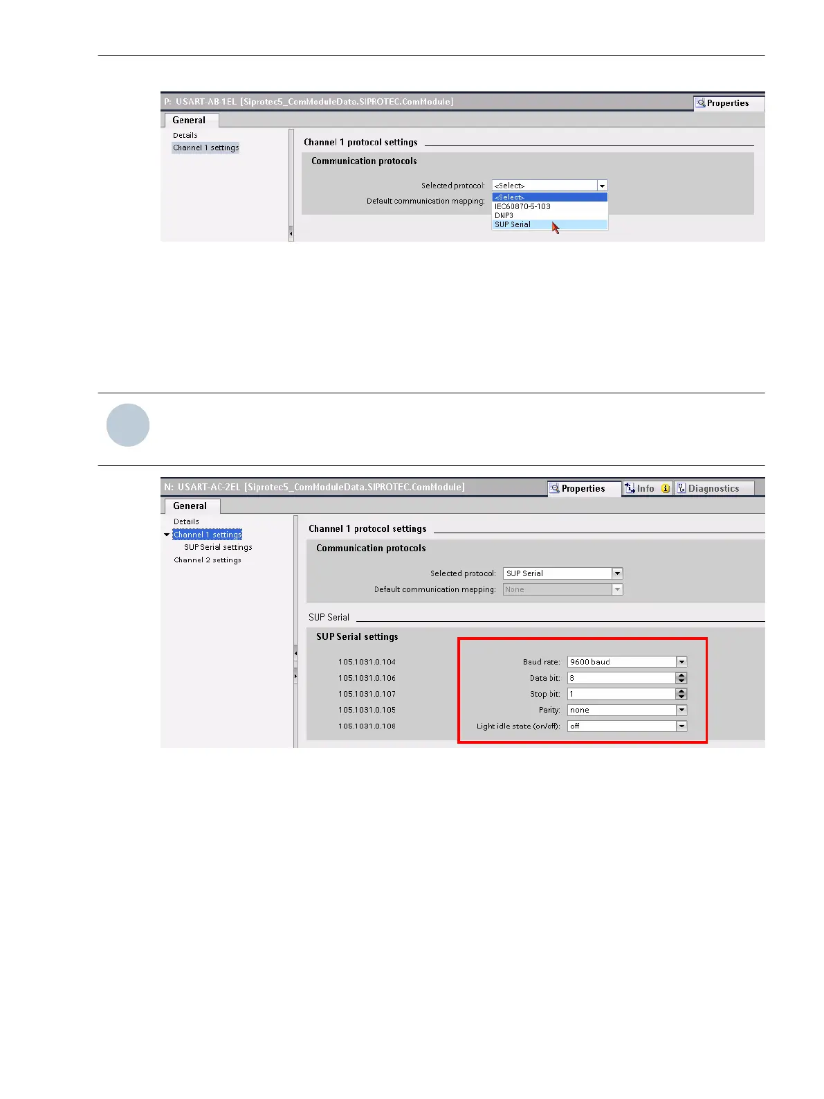
Figure 6-62 Selecting the SUP Protocol
Communication Settings
Make the communications settings for the relevant serial channels. For this, use the default settings specified
by the RTD box. Normally, you must adapt only the parameterization of the SIPROTEC 5 device to the settings
of the RTD box. Make sure that the setting values in both devices are the same. The settings of the Non-
flickering light (on/off): is not relevant for the RS485 interface.
NOTE
The driver for the USART module for the SUP protocol is not preinstalled as standard for the initial use of
this interface (following the firmware update).
[scauser5-220114-01-DE, 1, en_US]
Figure 6-63 Making the Communication Settings
With the selection of the SUP protocol for the RTD box DIGSI automatically adds the function group Analog
units to your device configuration. You can now instantiate the function RTD box serial 1 (refer to the
following figure).
Function-Group Types
6.5 Function-Group Type Analog Units
SIPROTEC 5, Fault Recorder, Manual 207
C53000-G5040-C018-5, Edition 11.2017

 Loading...


