[dw_measuring-transducer-characteristic, 1, en_US]
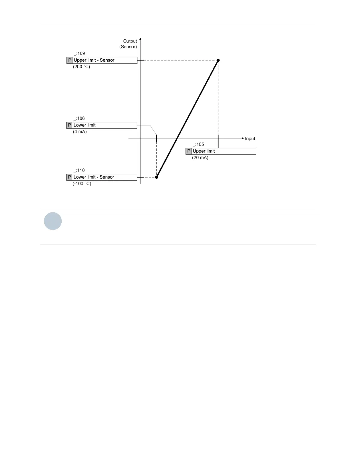
Figure 6-54
Characteristic Curve of Setting Example 1
NOTE
The hardware of the measuring transducer has been designed in such a way that measured values are
transmitted and analyzed using the setting range (Upper limit orLower limit). Therefore, special
applications are possible, if necessary. The limits are at approx. +20 mA and -20 mA or +10 V and -10 V.
Setting Example 2:
For special applications, the transmitter sends a maximum of ±12 V. This voltage shall be issued accordingly as
sensor voltage.
Set the parameters as follows:
•
Upper limit = 10.00 V
•
Upper limit - Sensor = 10.00 V
•
Lower limit = -10.00 V
•
Lower limit - Sensor = -10.00 V
With this setting, a signal of 12 V is issued as a 12-V measured value (see following figure).
Function-Group Types
6.5 Function-Group Type Analog Units
SIPROTEC 5, Fault Recorder, Manual 193
C53000-G5040-C018-5, Edition 11.2017

 Loading...


