EasyManuals Logo

Siemens SIPROTEC 5 User Manual

Siemens SIPROTEC 5
490 pages
To Next Page IconTo Next Page
To Previous Page IconTo Previous Page
Page #256 background imageLoading...
Page #256 background image
[dwtriwei-140213-01.tif, 1, en_US]
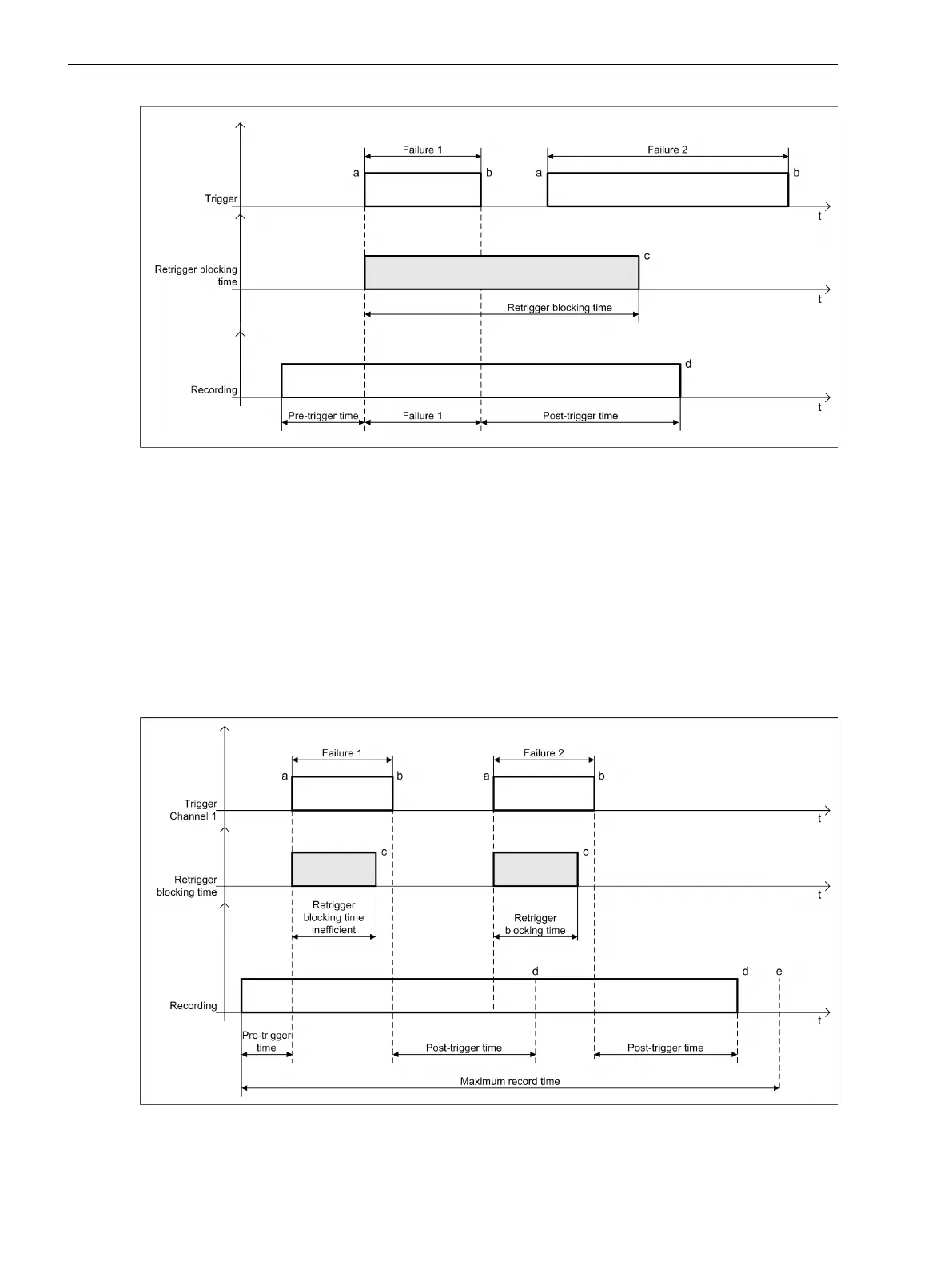
Figure 7-37 Other Triggers During the Retrigger Blocking Time
a Trigger rising edge: Start of the recording of the pre-trigger time and the retrigger blocking time
b Trigger falling edge: Start of the post-trigger time
c End of the retrigger blocking time
d End of recording
t Time line
When a trigger event occurs, the start trigger (a) trips a fault record.
The trigger event does not extend the recording due to the retrigger blocking time.
Trigger with Ineffective Retrigger Blocking Time
[dwtrig05-140213-02.tif, 1, en_US]
Figure 7-38 Trigger with Pre-Trigger Time, Post-Trigger Time, Maximum Record Time, and Ineffective
Retrigger Blocking Time
Fault Recorder
7.2 Function-Group Type Recorder
256 SIPROTEC 5, Fault Recorder, Manual
C53000-G5040-C018-5, Edition 11.2017

Table of Contents

Other manuals for Siemens SIPROTEC 5

Questions and Answers:

Question and Answer IconNeed help?

Do you have a question about the Siemens SIPROTEC 5 and is the answer not in the manual?

Siemens SIPROTEC 5 Specifications

General IconGeneral
SeriesSIPROTEC 5
Communication ProtocolsIEC 61850, DNP3, Modbus
CybersecurityRole-based access control, secure communication
Modular DesignYes
Hardware RedundancyOptional
Operating Temperature-25°C to +70°C
Digital InputsConfigurable, number depends on I/O modules
Digital OutputsConfigurable, number depends on I/O modules
Analog InputsConfigurable, number depends on I/O modules
Current Transformer InputsConfigurable, number depends on I/O modules
Voltage Transformer InputsConfigurable, number depends on I/O modules
Time SynchronizationIRIG-B, SNTP, PTP
Protection FunctionsOvercurrent, Differential, Distance, Over/Under Voltage, Frequency
Housing19-inch Rack Mount
DimensionsDepends on module configuration
WeightDepends on module configuration
Voltage Input24V DC, 48V DC, 110V DC, 125V DC, 220V DC, 250V DC

Related product manuals