[scmantrd-040613-01.tif, 1, en_US]
Figure 7-48 Manual Trigger Tripping via DIGSI 5
Manual Trigger Start via IEC 61850 Clients
The manual triggering of a fault record is possible from all connected IEC 61850 clients, e.g., SICAM PQS.
Information on this can be found in the manual of the appropriate device.
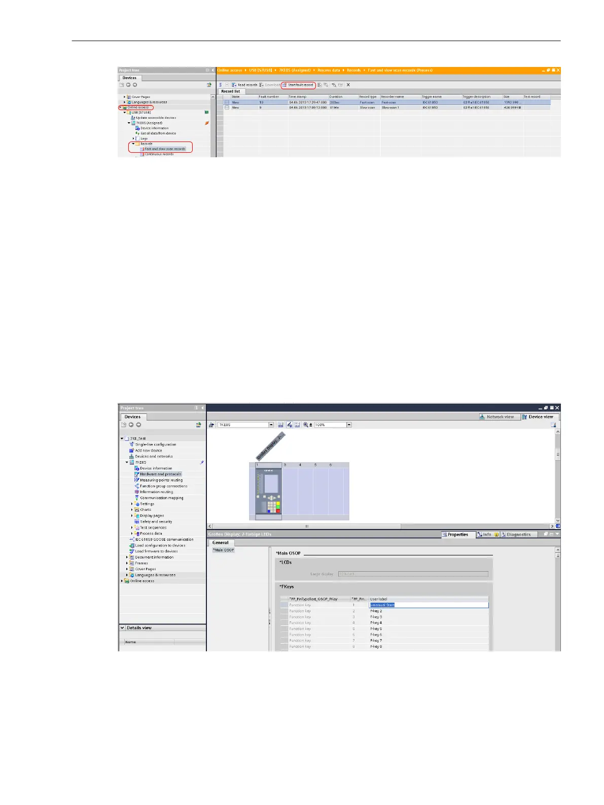
Changing the Function-Key Names in DIGSI 5
In the application templates, the manual trigger is the default on Function key 1 for the fast-scan recorder
and Function key 2 for the slow-scan recorder.
On the display in the device, Man. start fast-scan appears for F1 and Man. start slow-scan1 for F2.
If the signals for the function keys are re-routed, we recommend changing the names.
You can change the name of the manual trigger in DIGSI 5 using the following procedure:
•
Open your project in the project tree.
•
Double-click Hardware and protocols.
•
Click at the top right on the large device display.
•
Then click at the bottom on Properties, next on the function key of your choice and change the name.
[scfnkeys-191112-01.tif, 1, en_US]
Figure 7-49 Procedure When Changing the Function-Key Names
You can find more information on the default setting of function keys in the application templates in chapter
4.2 Application Template and Functional Scope for the Fault Recorder .
Fault Recorder
7.3 Function Description Analog and Binary Triggers
SIPROTEC 5, Fault Recorder, Manual 267
C53000-G5040-C018-5, Edition 11.2017

 Loading...


