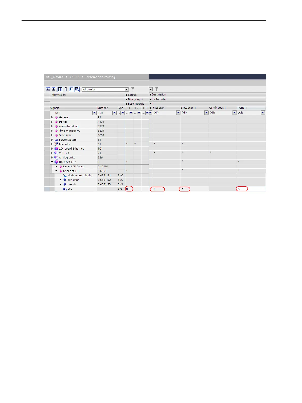
EasyManuals Logo

Siemens SIPROTEC 5 User Manual

Siemens SIPROTEC 5
490 pages
To Next Page IconTo Next Page
To Previous Page IconTo Previous Page
Page #270 background imageLoading...
Page #270 background image
Open the User-defined signals folder and add an SPS indication to the user-defined function block.
Open the information routing.
Route the SPS indication to a binary input by selecting the routing option H. The SPS signal is thereby
routed as active with voltage.
Move the menu bar from left to right and route the SPS indication to the recorder as desired.
[ScTrigDevInd-010715, 1, en_US]
Figure 7-52 Procedure: Trigger on SPS Indication
Fault Recorder
7.3 Function Description Analog and Binary Triggers
270 SIPROTEC 5, Fault Recorder, Manual
C53000-G5040-C018-5, Edition 11.2017

Table of Contents

Other manuals for Siemens SIPROTEC 5

Questions and Answers:

Question and Answer IconNeed help?

Do you have a question about the Siemens SIPROTEC 5 and is the answer not in the manual?

Siemens SIPROTEC 5 Specifications

General IconGeneral
SeriesSIPROTEC 5
Communication ProtocolsIEC 61850, DNP3, Modbus
CybersecurityRole-based access control, secure communication
Modular DesignYes
Hardware RedundancyOptional
Operating Temperature-25°C to +70°C
Digital InputsConfigurable, number depends on I/O modules
Digital OutputsConfigurable, number depends on I/O modules
Analog InputsConfigurable, number depends on I/O modules
Current Transformer InputsConfigurable, number depends on I/O modules
Voltage Transformer InputsConfigurable, number depends on I/O modules
Time SynchronizationIRIG-B, SNTP, PTP
Protection FunctionsOvercurrent, Differential, Distance, Over/Under Voltage, Frequency
Housing19-inch Rack Mount
DimensionsDepends on module configuration
WeightDepends on module configuration
Voltage Input24V DC, 48V DC, 110V DC, 125V DC, 220V DC, 250V DC

Related product manuals