[dwlotrif-161012-01.tif, 1, en_US]
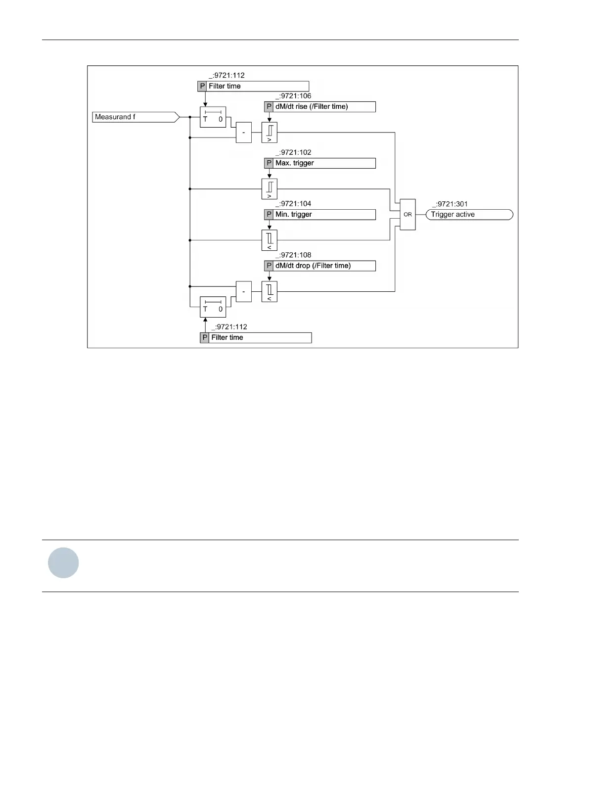
Figure 7-58
Logic Diagram of the Frequency Trigger
The function Frequency trigger is subdivided intoLevel and Gradient trigger.
The Level trigger monitors the measurand for minimum and maximum limit violations. The Gradient trigger
monitors the positive slope (increasing) and the negative slope (decreasing) of the measurand for a limit viola-
tion. The gradient is formed based on the set filtering time.
A hysteresis of 0.2 % of the setting value is preset for the level and gradient triggers. This is equal to 0.998
p.u. for the max. and gradient trigger and to 1.002 p.u. for the Min. trigger.
Exceeding or dropping below one of the set threshold value leads to trigger tripping. The trigger tripping is
however effective on the recorders only if you have routed the trigger on the recorder.
Function Block
The Frequency trigger contains the function block Frq. Trigger 1, with which you can set the trigger for
monitoring the power frequency.
NOTE
The thresholds can be set in the primary, secondary, and percentage view. All subsequent setting values
are shown in the secondary view.
Mode
The trigger is switched on, off, or in test mode. In test mode, the fault records are marked with a test flag.
You can find more detailed information on the mode in chapter 7.1.3 Step 2: Setting the Parameters and
Routing in DIGSI 5 .
Max. Trigger Active/Min. Trigger Active
With the parameters Max. trigger active and Min. trigger active, you can define whether the
respective level trigger is active or inactive.
Fault Recorder
7.4 Trigger Functions 1-Phase
286 SIPROTEC 5, Fault Recorder, Manual
C53000-G5040-C018-5, Edition 11.2017

 Loading...


