PQ Trend
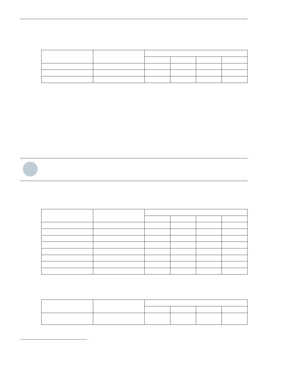
Table 7-14 Using PQ Trend Measurands
Measurand Refresh Rate Use in
FSR SSR CR TR
PQ trend:f Event-based X X
PQ trend:Vph rms Event-based X X
PQ trend:Vpp rms Event-based X X
PQ Flicker
The short-term flicker severity P
st
PQ flicker and the long-term flicker severity P
lt
PQ flicker are determined for
phase-to-ground and delta voltages (depending on the connection type). The flicker is measured in all 3
voltage channels of the corresponding feeder. Flicker appear with a frequency between 0.005 Hz and 35 Hz.
The flicker severity is determined as follows:
•
Short-term flicker severity P
st
: over 10 minutes (short-term flicker), permanently set
•
Long-term flicker severity P
lt
: over 2 hours (12 P
st
values), permanently set
•
Instantaneous value of flicker perception P
inst
19
•
P
imx
: Maximum value of flicker perception P
inst
NOTE
P
inst
and P
imx
serve as the qualification of the flicker algorithm and are not available for long-term recording.
You will find information about the average value, the refresh rate, and the recommended routing of the
frequency measurands in the following table.
Table 7-15
Using Flicker Measurands
Measurand Refresh Rate Use in
FSR SSR CR TR
PQ flicker:Pst ph 10 min X X
PQ flicker:Plt ph 2 h X X
PQ flicker:Pinst ph 12 ms X
PQ flicker:Pimx ph 12 ms X
PQ flicker:Pst pp 10 min X X
PQ flicker:Plt pp 2 h X X
PQ flicker:Pinst pp 12 ms X
PQ flicker:Pimx pp 12 ms X
Other Measured Values (No Recorder Routing Measured Values)
Table 7-16
Using Other Measured Values
Measurand Refresh Rate Use in
FSR SSR CR TR
For example, operational
measured values
For example, 180 ms X
19
Pinst is designated as output 5 in the former version of the standard.
Fault Recorder
7.6 Measurands and Recorder Routing Functions
352 SIPROTEC 5, Fault Recorder, Manual
C53000-G5040-C018-5, Edition 11.2017

 Loading...


