Logic
[locssumm-140611-01.tif, 3, en_US]
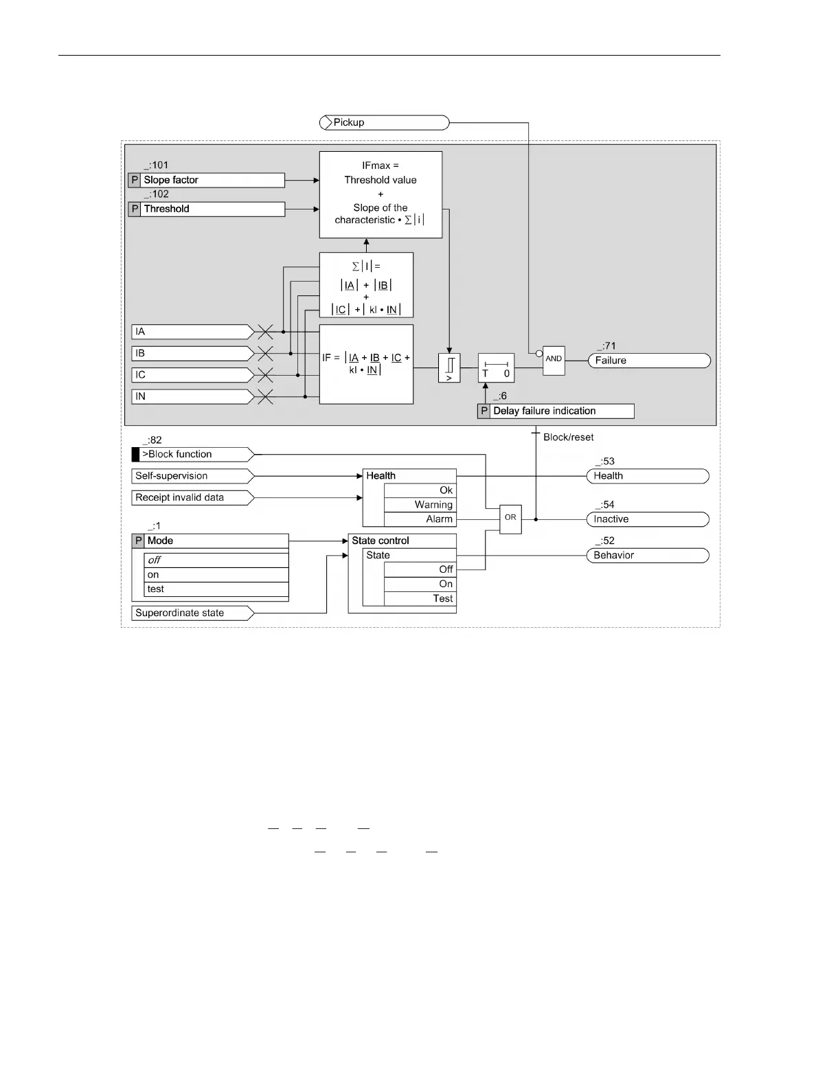
Figure 8-20
Logic Diagram of the Current-Sum Supervision
Slope of the Characteristic Curve
The Slope factor • Σ | I | part takes into account permissible current-proportional transformation errors of
the transformer, which can occur in the case of high short-circuit currents.
The Slope factor and Threshold parameters are used to set the fault-current limit (I
Fmax
) for the current-
sum supervision. The device calculates this fault current limit with the formula:
I
Fmax
= Threshold + Slope factor • Σ| I |
The device uses the current inputs (IA, IB, IC and IN) to calculate:
•
The fault current IF = |
IA + IB + IC + kl• IN|
•
The maximum current Σ| I | = |
IA| + |IB| +| IC| + |kl• IN|
with k
I
taking into account a possible difference from the transformation ratio of a separated ground-current
transformer (I
N
), for example, cable type current transformer.
•
Transformation ratio of residual-current converter: Ratio
N
•
Transformation ratio of phase-current converter: Ratio
ph
Supervision Functions
8.3 Supervision of the Secondary System
388 SIPROTEC 5, Fault Recorder, Manual
C53000-G5040-C018-5, Edition 11.2017

 Loading...


