NOTE
The switchover of current polarity at the 3-phase current transformer causes a rotation in the direction of
electric current for current input I4 (I
N-sep
)!
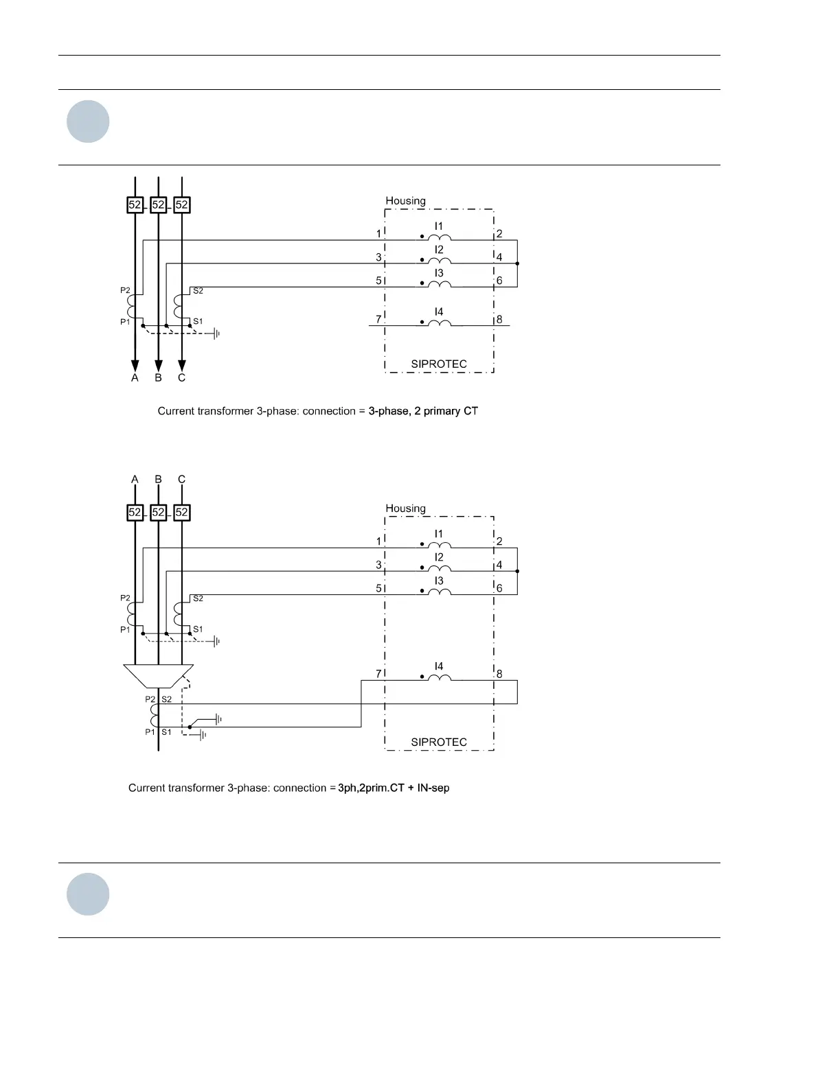
[tileite7-070211-01.tif, 3, en_US]
Figure A-9 Connection to a 2-Wire Current Transformer - for Isolated or Resonant-Grounded Systems Only
[tileite8-260313-01.tif, 3, en_US]
Figure A-10 Connection to a 2-Wire Current Transformer and Cable Type Current Transformer for Sensitive
Ground-Fault Detection - for Isolated or Resonant-Grounded Systems Only
NOTE
The switchover of current polarity at the 3-phase current transformer causes a rotation in the direction of
electric current for current input I4 (I
N-sep
)!
Appendix
A.4 Connection Examples for Current Transformers
464 SIPROTEC 5, Fault Recorder, Manual
C53000-G5040-C018-5, Edition 11.2017

 Loading...


