Building Blocks Description
BUILD_ACD
BUILD_ACT
BUILD_BSC
BUILD_DPS
BUILD_ENS
BUILD_SPS
BUILD_XMV
These building blocks merge data value and quality. The building-block output is generally
used as a CFC output.
Generally, the BUILD_Q building block is connected upstream from these building blocks.
CFC charts have a standard behavior in the processing of signals. If an input signal of the CFC chart has the
quality
invalid
, all output signals of the CFC chart also get the quality
invalid
. This standard behavior is
not desirable in some applications. If you use the building blocks for quality processing, the quality attributes
of the input signals in the CFC chart are processed.
EXAMPLE: Switchgear Interlocking via GOOSE
The following conditions apply to the example:
•
The interlocking condition for switchgear interlocking protection is stored in the device as a CFC chart.
•
The removed device sends the release signal for the interlocking condition via a GOOSE telegram.
If the communication connection has been interrupted, the release signal (GOOSEStr) incoming via the
GOOSE telegram gets the quality
invalid
. If the CFC chart obtains an invalid input signal, there are the
following possibilities: The last signal valid before the communication interruption is used (quality =
good
) or
a substitute data value with the quality
good
is used (True, False).
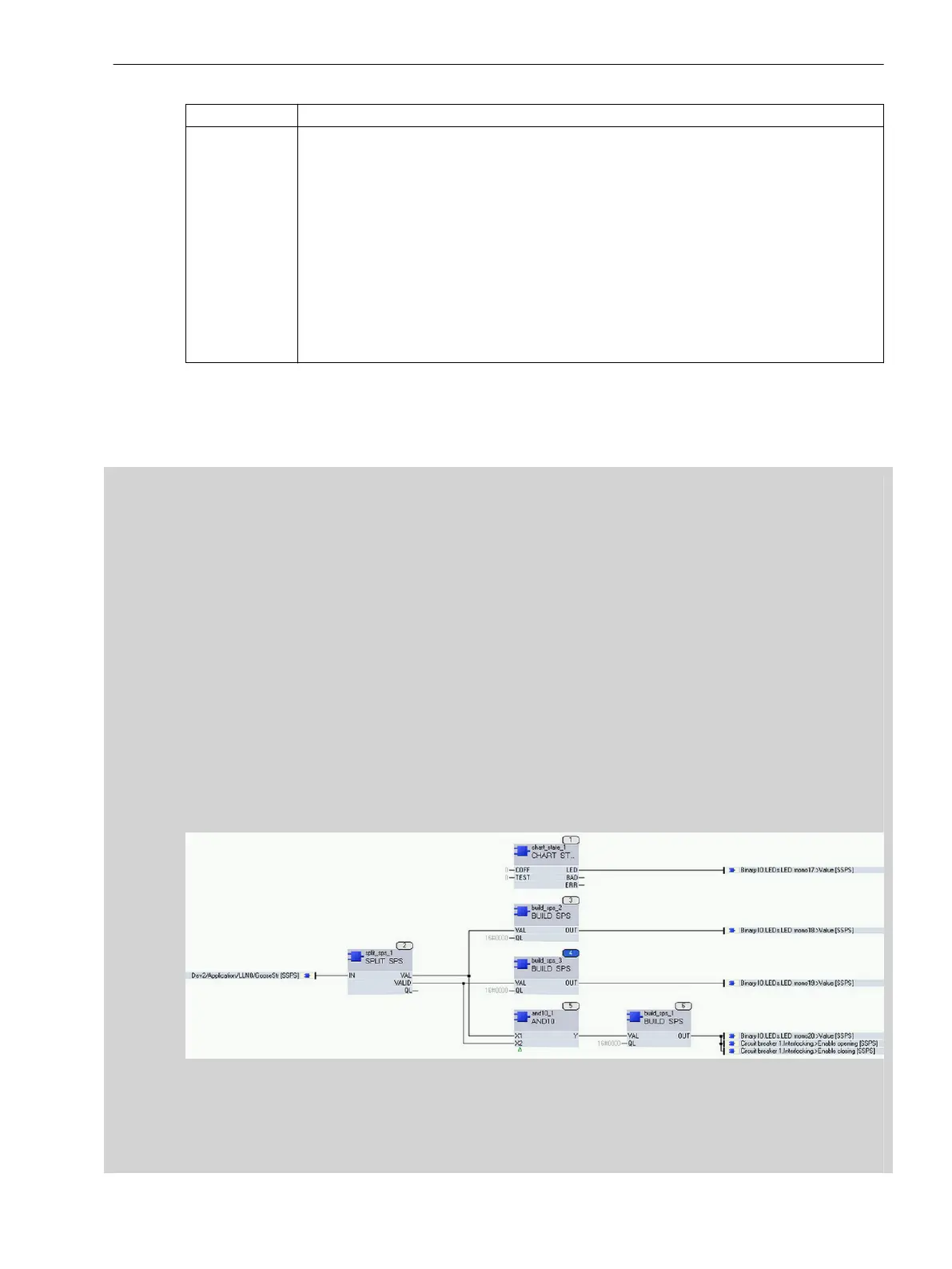
To do this, you have to create a separate CFC chart in addition to the interlocking plan of the switchgear inter-
locking. Use the building blocks for quality processing in a separate CFC chart. With the SPLIT_SPS building
block, split the input signal (data type = SPS) into data value and quality information. You can then continue to
process these signals separately in the CFC chart. Use the quality information as an input signal for a
BUILD_SPS building block and assign the quality
good
to the signal. You obtain an SPS signal as a result, with
the quality
good
. You can use this to process release messages correctly. You can process the release
messages with the quality
good
in the CFC chart of the actual interlocking. Therefore, the release signal for a
switch illustrated in the interlocking logic is available as a valid result with the quality
good
. The following
figure shows an example of the CFC chart with the building blocks for quality processing:
[sccfcran-220415-01, 1, en_US]
Figure 3-29 CFC Chart with Building Blocks for Quality Processing (Switchgear Interlocking via GOOSE)
If you do not want to convert the invalid release signal to a valid signal, as described, during the communica-
tion interruption, you can also assign a defined data value to the release signal. Proceed as follows: With the
SPLIT_SPS building block, split the input signal (data type = SPS) into data value and quality information. Link
System Functions
3.3 Processing Quality Attributes
SIPROTEC 5, Fault Recorder, Manual 77
C53000-G5040-C018-5, Edition 11.2017

 Loading...


