Chatter blocking can be activated or deactivated as a parameter of the position in the General function block.
The parameters for the chatter blocking are set centrally the same for the entire device in DIGSI. in the Device
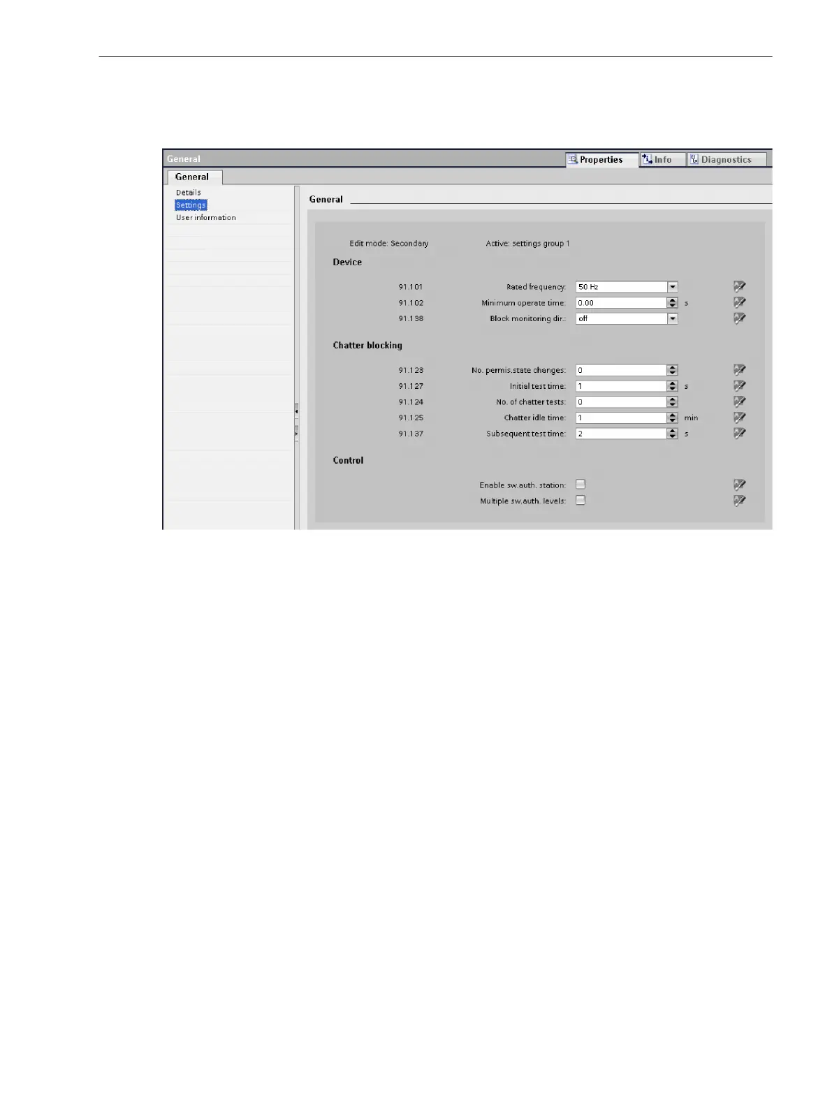
settings (see the next figure for this).
[scfla7ke-260213-01.tif, 1, en_US]
Figure 3-40
Setting Chatter Blocking
The chatter-blocking settings have the following meaning (see Figure 3-41):
•
Number of permissible status changes
This number specifies how often the state of a signal may toggle within the chatter-test time and the
chatter-checking time. If this number is exceeded, the signal will be or remains blocked.
Enter a number from 0 to 65535 in this field. If the entry is 0, chatter blocking is essentially inactive.
•
Chatter test time
During this time, the number of times a signal changes its state is checked. This time is started if chatter
blocking is configured for at least one signal and this signal changes its state. When the set time has
expired, the timer restarts automatically (cycle time).
Enter a number between 1 and 65535 in this field. The number entered corresponds to the time in
seconds.
•
Number of chatter tests
This number specifies the maximum number of test cycles to be run before the signal is finally blocked. In
this case the indications Group warning (Alarm handling group) and Chatter blocking (Device group)
are set. Restarting the devices removes this block again.
Enter a number from 0 to 32767 in this field. The value Infinite (∞) is permissible here.
Enter this value as character string oo.
•
Chatter dead time
If the number of permissible status changes for a signal is exceeded during the first chatter-test time or
the second chatter-test time, the chatter dead time starts. This signal is blocked within this time.
Enter a number between 1 and 65535 in this field. The number entered corresponds to the time in
minutes. An entry is possible here only if the number of chatter checks does not equal 0.
Example: If, for instance, you enter 1 min. here and chatter blocking starts for a signal, the actual dead
time may lie between 1 min., and 1 min. and 59 s.
System Functions
3.6 Other Functions
SIPROTEC 5, Fault Recorder, Manual 93
C53000-G5040-C018-5, Edition 11.2017

 Loading...


