147
Feed-In Management
Channel settings for power reduction section
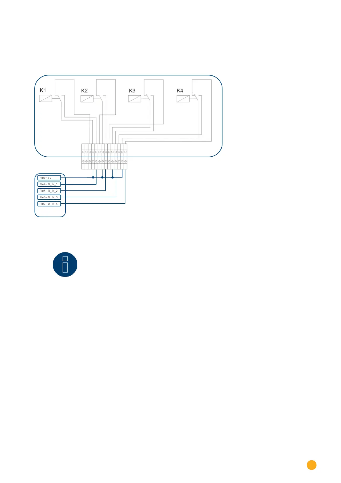
The relay outputs for the ripple control receiver are connected to the PM+ input of the Solar-Log™ PM+.
This allows the grid operator's signals to be evaluated by the Solar-Log™.
Fig.: Schematic diagram of a ripple control receiver with four relays.
The relay for active power control is wired to the PM+ interface.
Note!
The function of the PM+ interface is only possible when the contacts of the ripple control
receiver are potential free and are wired with a supply voltage of 5VDC from the PM+
interface.
In practice, various ripple control receivers with varying numbers of relays and different signal codes are
used. The configuration matrix for the Solar-Log™ PM+ thus offers maximum flexibility – most common ver-
sions can be configured.
Ripple control receivers generally possess 2 to 5 relays. The assignment of the individual relay states for
certain reduction levels is specified by the respective network operator and stored in the Solar-Log™ using
this matrix. In this way the connected inverters can be adjusted to meet the specified reduction levels.