63
Other connections
13.2 Relay (only Solar-Log 1000, 1200 and 2000)
The Solar-Log™ has a potential-free control relay, which is activated under the following conditions:
•
Alarm contact triggered
•
Active power reduction activated
•
Optimization of self-consumption
The relay may be loaded with a maximum of 24 V DC and 2 A.
A 230 V appliance has to be connected via another load relay.
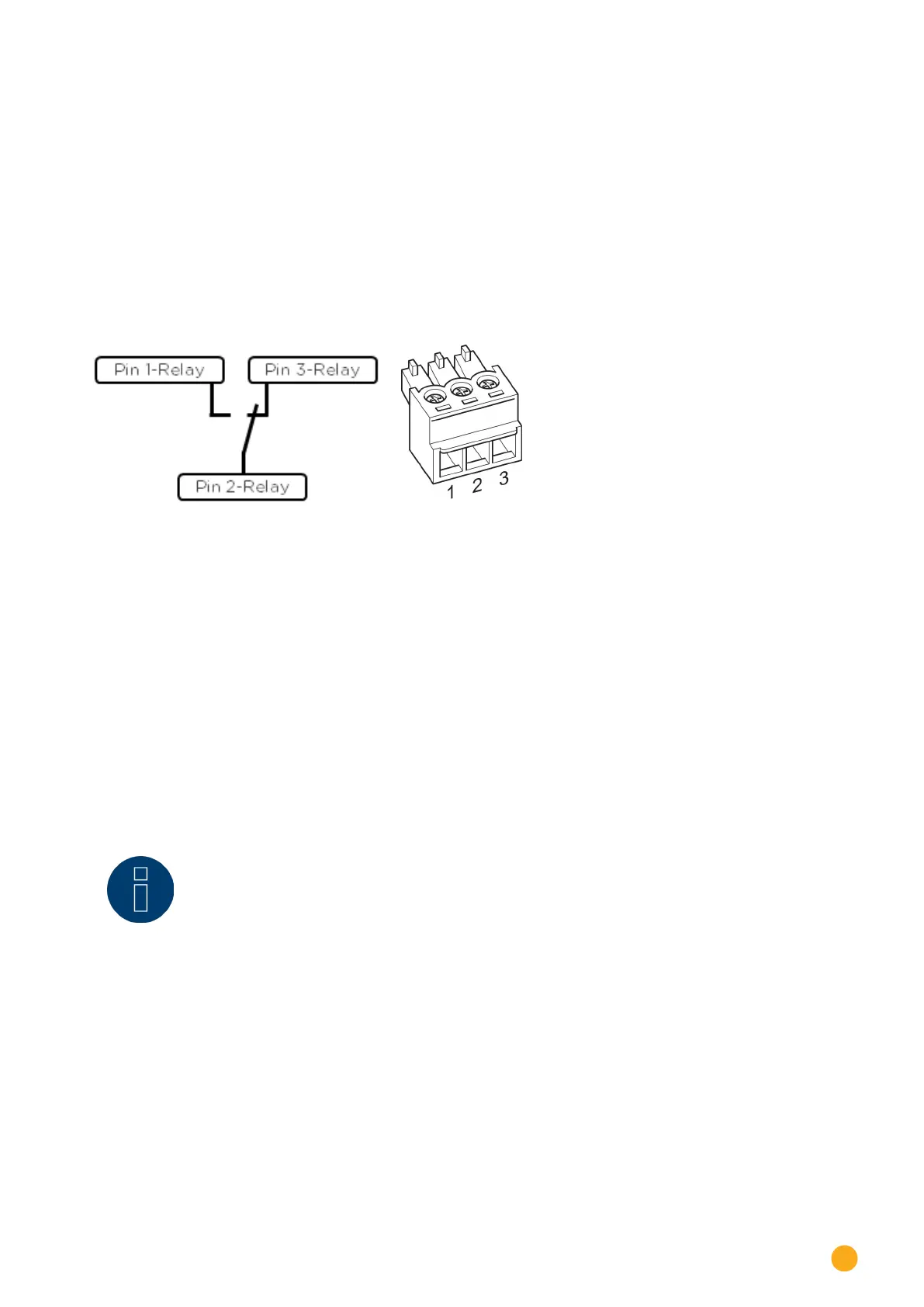
Connection
Fig.: Relay connection diagram
Wiring
The wiring is done using the supplied 3-pin connector;
usually pin 1 and pin 2 are used.
In the Off state,
•
pin 1-2 are open
•
and pin 2-3 are closed.
In the On state (alarm/fault/power reduction activated),
•
and pin 1-2 are closed.
•
pin 2-3 are open
Note!
If a relay is used for the optimization of self-consumption, it has to be defined as a switch
and recognized (see Chapter 18.1.1. "Configuring the device interface").
The operating states are then recorded.