EasyManuals Logo

Solar-Log 2000 Installation Manual

Solar-Log 2000
224 pages
To Next Page IconTo Next Page
To Previous Page IconTo Previous Page
Page #90 background imageLoading...
Page #90 background image
90
Configuring connected devices
Note!
The number behind the interface (e.g. x1) indicates the number of switching devices for
this device type.
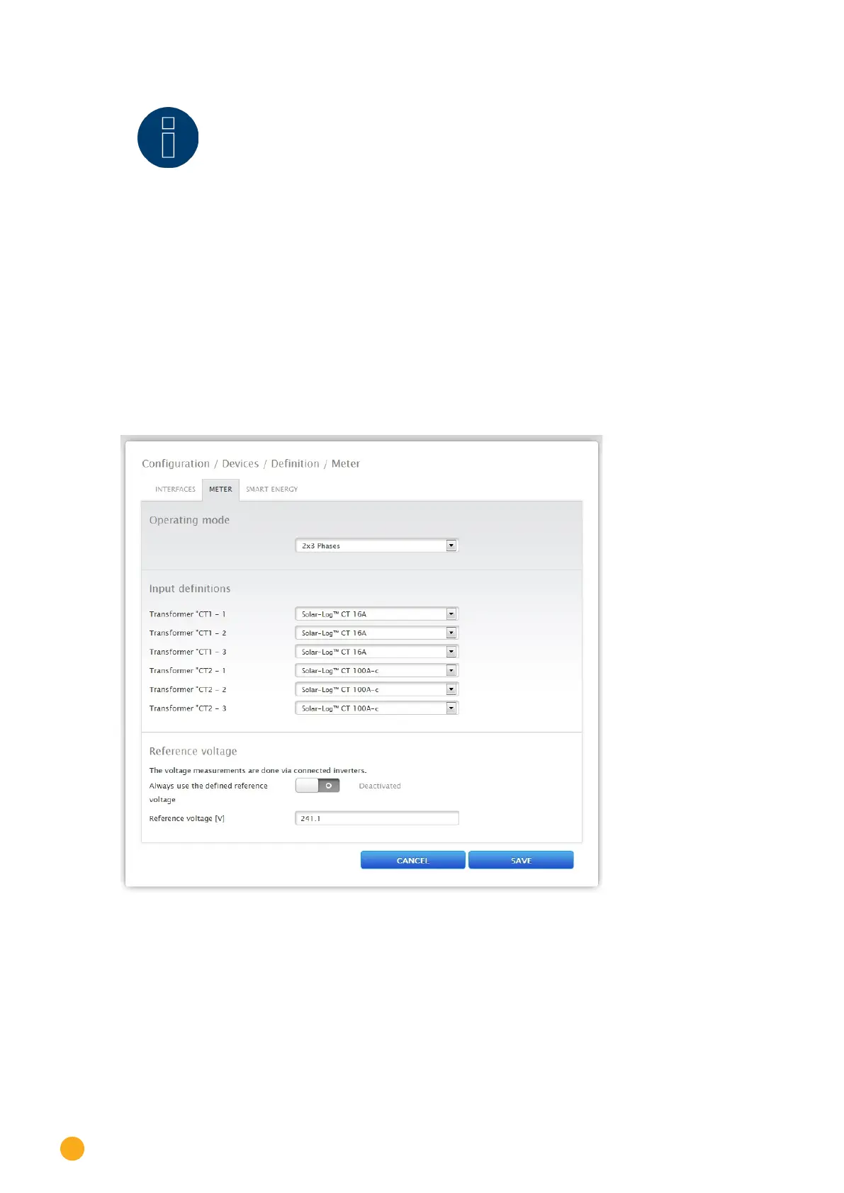
18.2 Defining the Solar-Log™ Meter (only Solar-Log™ Meter)
With this model version, an extra tab Meter is displayed in the Configuration | Devices | Definition menu.
The following setting options are available from this tab:
Input definition
Reference voltage
The Operating Mode section describes the setting for the various operating modes of the Solar-Log™
Meter and is to be selected in the Device Definition before Device Detection. (See figure "Operating mode
Solar-Log™ Meter)“
Fig.: Device denition for the Solar-Log™ Meter

Table of Contents

Other manuals for Solar-Log 2000

Questions and Answers:

Question and Answer IconNeed help?

Do you have a question about the Solar-Log 2000 and is the answer not in the manual?

Solar-Log 2000 Specifications

General IconGeneral
Device TypeData Logger
Max Inverters100
Power Supply24 V DC
Remote MonitoringYes
Ethernet interfaceYes
Communication InterfacesRS485, Ethernet
ProtocolsModbus
Data StorageInternal

Related product manuals