EasyManuals Logo

Solar-Log 2000 Installation Manual

Solar-Log 2000
224 pages
To Next Page IconTo Next Page
To Previous Page IconTo Previous Page
Page #58 background imageLoading...
Page #58 background image
58
Connecting accessories
Note!
The Solar-Log™ Smart Relay Box cannot be connected together with inverters on an
RS485 interface. The Relay Box requires its own separate RS485 bus.
It is possible to combine the Utility Meter with sensors.
Note!
The Solar-Log™ Smart Relay Box cannot be connected together with PM+ packages on a
Solar-Log™.
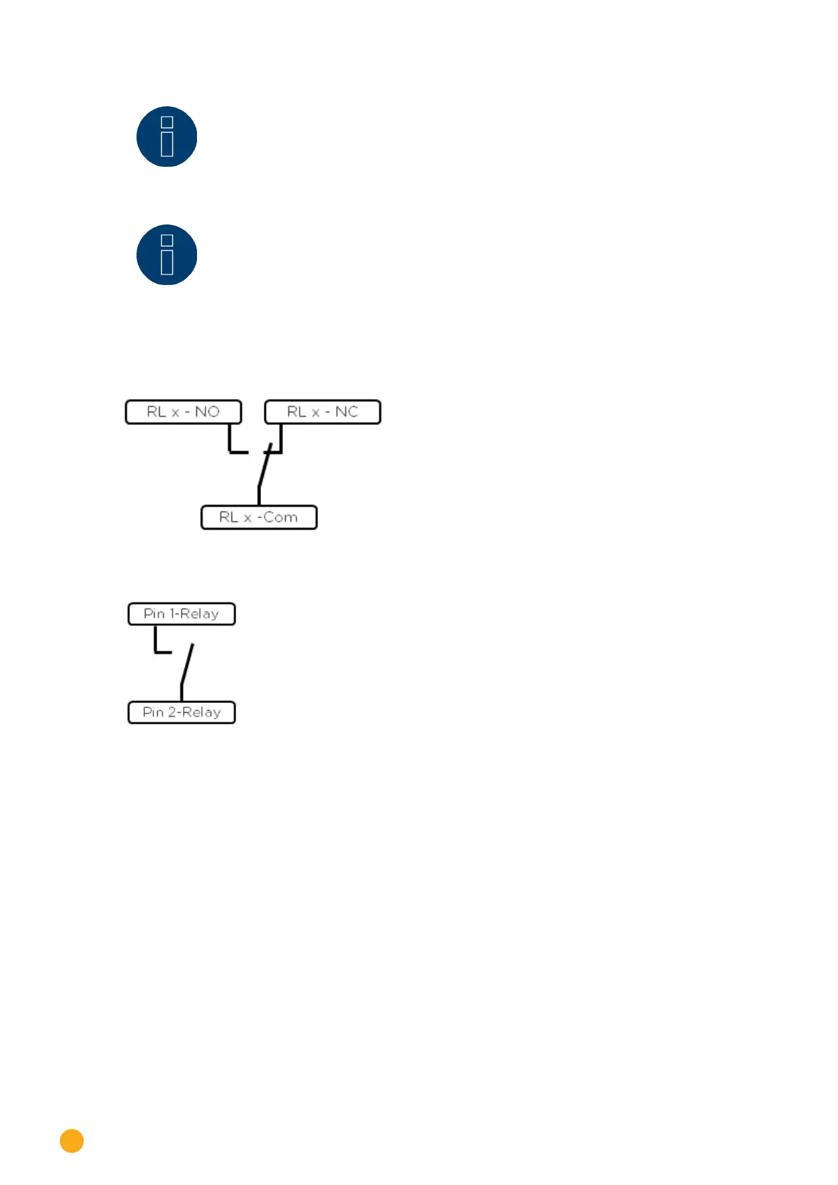
Relay output assignments
Fig.: Smart Relay Box relay output (change-over contact) diagram
Fig.: Smart Relay Box relay output (make contact) diagram

Table of Contents

Other manuals for Solar-Log 2000

Questions and Answers:

Question and Answer IconNeed help?

Do you have a question about the Solar-Log 2000 and is the answer not in the manual?

Solar-Log 2000 Specifications

General IconGeneral
Device TypeData Logger
Max Inverters100
Power Supply24 V DC
Remote MonitoringYes
Ethernet interfaceYes
Communication InterfacesRS485, Ethernet
ProtocolsModbus
Data StorageInternal

Related product manuals