215
Appendix
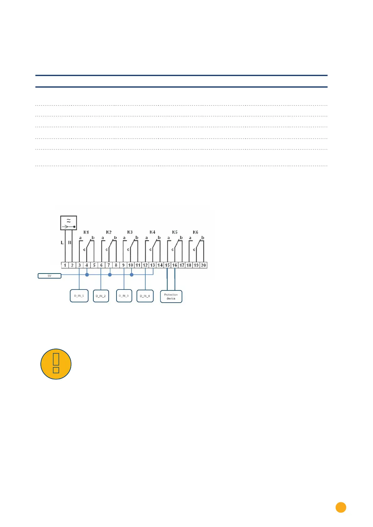
31.4.4 Variation with 5 relays (including emergency stop)
Specifications
Ripple control receiver signals
Level K1 K2
K3 K4 K5
Power out-
put
1 On Off Off Off Off 100%
2 Off On Off Off Off 60%
3 Off Off On Off Off 30%
4 Off Off Off On Off 0%
5 On Emergency
stop
The relay is continuously activated for a particular level (condition). There is always only one relay that is
activated.
Wiring
Fig.: Wiring a ripple control receive with two relays - example 4
Warning!
Emergency stop commands may not be processed via the Solar-Log™ These com-
mands have to function directly with the corresponding protection equipment such as
grid and plant protection, section switches and Q/U protection.
 Loading...


