EasyManuals Logo

Solar-Log 2000 Installation Manual

Solar-Log 2000
224 pages
To Next Page IconTo Next Page
To Previous Page IconTo Previous Page
Page #216 background imageLoading...
Page #216 background image
216
Appendix
Connecting PM+ terminal connector
and ripple control receiver
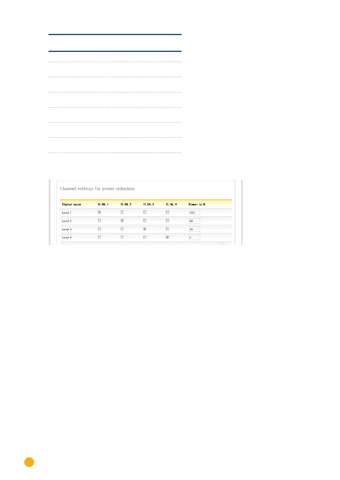
PIN Assignment Meaning
1 +5V Control voltage for active
power
2 D_IN_1 Level 1
100%
3 D_In_2 Level 2
60%
4 D_In_3 Level 3
30%
5 D_In_4 Level 4
0%
6 +5V Control voltage for reac-
tive power (unused)
Configuration in browser menu
Remote controlled active power reduction Configuration | Feed-in Management | Active Power
Fig.: Channel settings for active power reduction - example 4

Table of Contents

Other manuals for Solar-Log 2000

Questions and Answers:

Question and Answer IconNeed help?

Do you have a question about the Solar-Log 2000 and is the answer not in the manual?

Solar-Log 2000 Specifications

General IconGeneral
Device TypeData Logger
Max Inverters100
Power Supply24 V DC
Remote MonitoringYes
Ethernet interfaceYes
Communication InterfacesRS485, Ethernet
ProtocolsModbus
Data StorageInternal

Related product manuals