35
Connector Assignments and Wiring
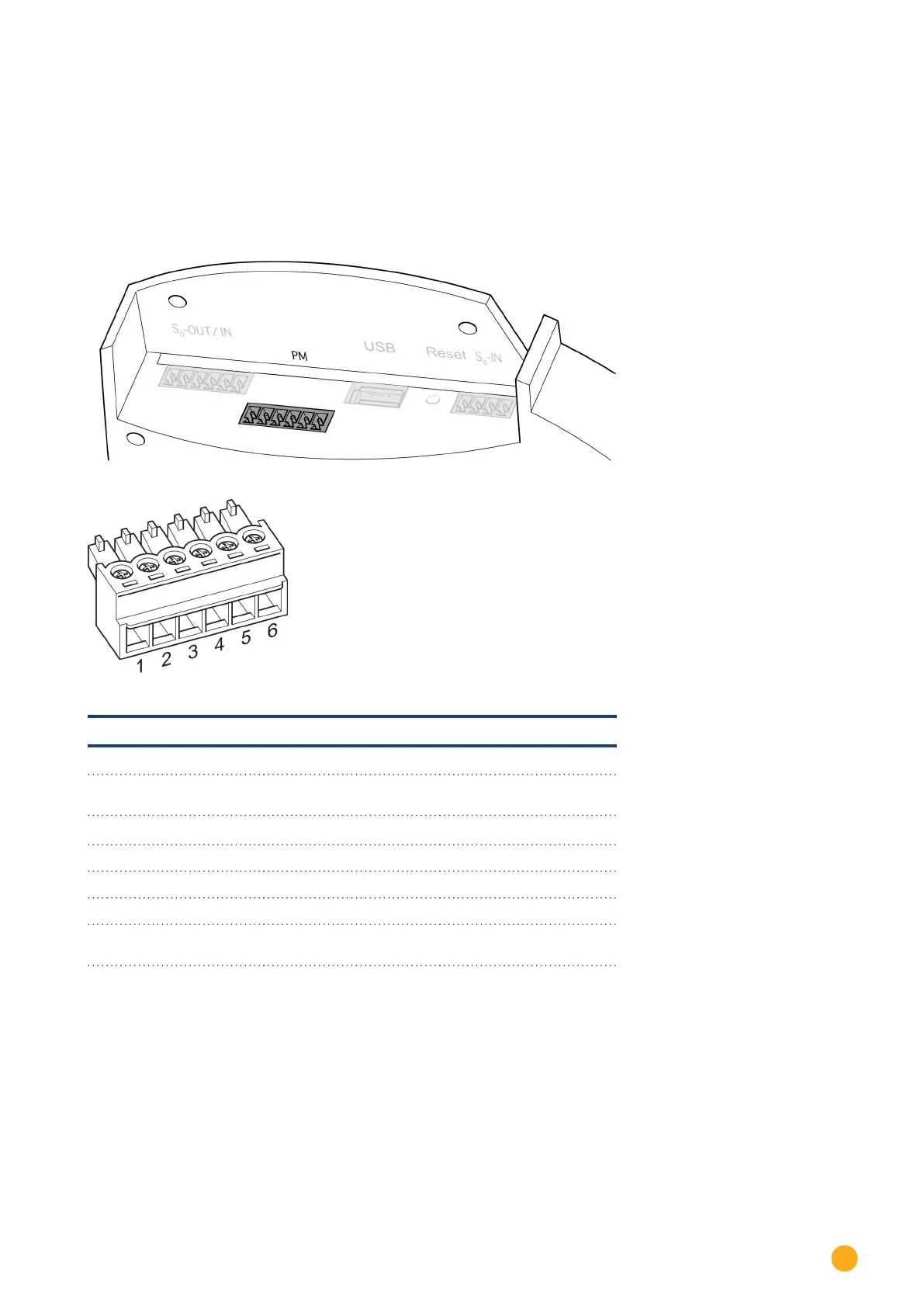
10.6 PM+
The Solar-Log™ PM+ models come with a 6-pin PM+ interface on the top side of the Solar-Log
TM
.
The interface has been designed to link the ripple control receivers or telecontrol plants with potential-free
signal contacts. Up to two ripple control receivers can be connected. This allows the commands from grid
operators for active and reactive power to be interpreted.
Fig.: 6-pin PM+ interface
Fig.: 6-pin Terminal block connector
PM+
PIN Assignment Description
1 +5V Control voltage for active
power control
2 D_IN_1 Control input 1
3 D_In_2 Control input 2
4 D_In_3 Control input 3
5 D_In_4 Control input 4
6 +5V Control voltage for reactive
power reduction
To provide the highest possible flexibility, the individual active and reactive power values can be assigned
to inputs D_IN_1 to D_IN_4
See Chapter „Feed-In Management“for more information
See the appendix for more ripple control receiver connection examples