160
Feed-In Management
In practice, various ripple control receivers with varying numbers of relays and different signal codes are
used. The configuration matrix for the Solar-Log™ PM+ thus offers maximum flexibility – most common ver-
sions can be configured.
Ripple control receivers generally possess 2 to 5 relays. The assignment of the individual relay states for a
particular shift factor is specified by the respective grid operator and stored in the Solar-Log™ using this
matrix. In this way the connected inverters can be adjusted to meet the specified reduction levels.
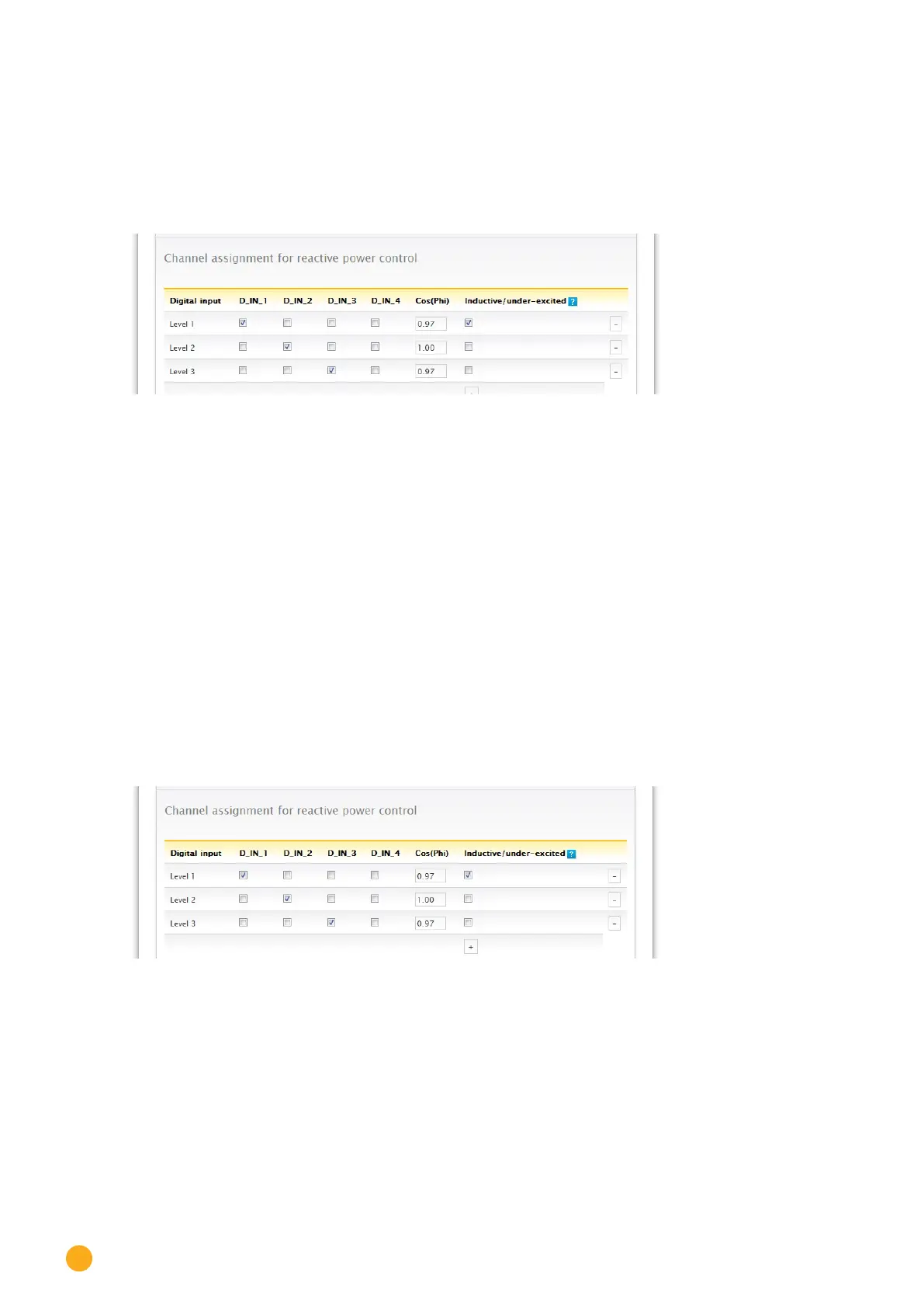
Fig.: Channel settings for remote controlled cos (Phi)
For each level, the input signal combination and a value for the shift factor in cos (Phi) is entered.
Checking the box next to the digital inputs of the PM+ interface (D_IN_1 to D_IN_4) means that the input is
supplied with 5V from pin 6 to reduce the output on the cos phi defined in the box "cos (Phi)".
Four levels are shown in the basic setting. The "+" sign can be used to extend the list by additional levels.
Procedure:
•
Select remote controlled.
•
Select the inverter(s) to control in the Interface assignments section.
•
Enter the channel settings for power reduction according to the specifications and wiring.
•
Select options.
•
SAVE the settings.
More Options
Switching from the remote-controlled cos (Phi) to the possible characteristic curves can be implemented
via assigned combinations of signals to the PM+ interface.
Fig.: Switching to reactive power characteristic curves with certain signals
If a switch to the characteristic curve operating mode (P/Pn and Q(U)) is required due to a certain ripple
control receiver signal, the respective levels for the switch can be entered in the input box. If no switch
should take place, enter 0 in the input box.
When the switch is activated, the configuration page reloads itself. The corresponding characteristic
curves need to be defined. The settings for the characteristic curves correspond to the procedures de-
scribed in „24.1.5 Variable reactive power via the characteristic curve Q(U) (only Solar-Log 2000 with Util-
ity Meter)”

 Loading...


