62
Other connections
13 Other connections
13.1 Alarm contact (only Solar-Log 1000 and 2000)
The Solar-Log 1000 and 2000 have an alarm contact which is triggered if the connection is broken.
This function can be used for various applications:
•
Anti-theft protection for the modules or inverters
•
For wiring to the mounting frame or to the modules, use a thin weather-resistant cable that breaks
when strained. The maximum cable length is around 500 meters.
•
Access control via door contact
•
Monitoring of circuit breakers
•
Connection to an uninterruptible power supply (UPS).
If the connection is broken, the Solar-Log™ can carry out the following actions:
•
Switch a relay
•
Send e-mail
•
Send text message (SMS)
•
Produce an audible signal
The notification actions can be set on the Solar-Log 2000 in the section Configuration | Notifications |
Alarm .
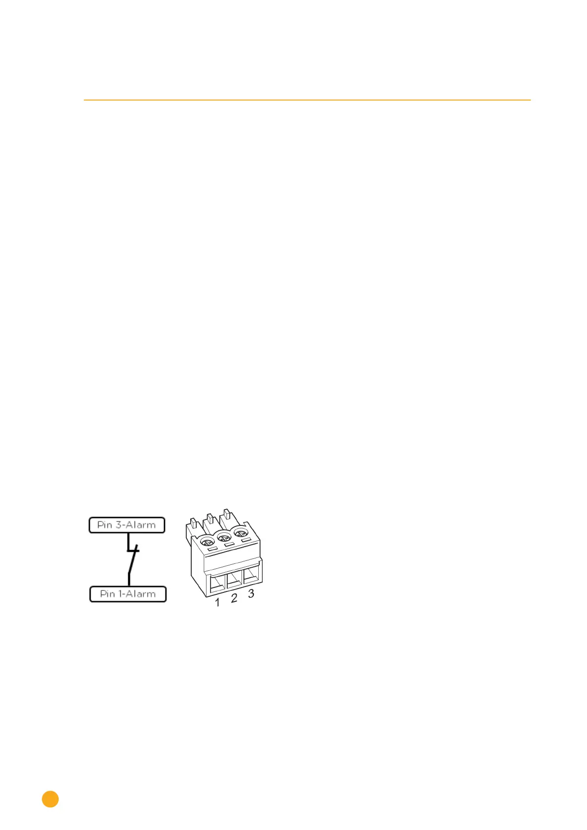
Connection
The connection is done using a 3-pin terminal block connector according to the following diagram:
Fig.: Alarm contact connection diagram
If the connection between pin 1 and pin 3 is broken, the alarm is triggered. and the configured action is car-
ried out.

 Loading...


