157
Feed-In Management
24.3.5 Variable reactive power via the characteristic curve Q(U)
(only Solar-Log 2000 with Utility Meter)
In order to be able to achieve this function, the Solar-Log™ Utility Meter is required in addition to a
Solar-Log 2000.
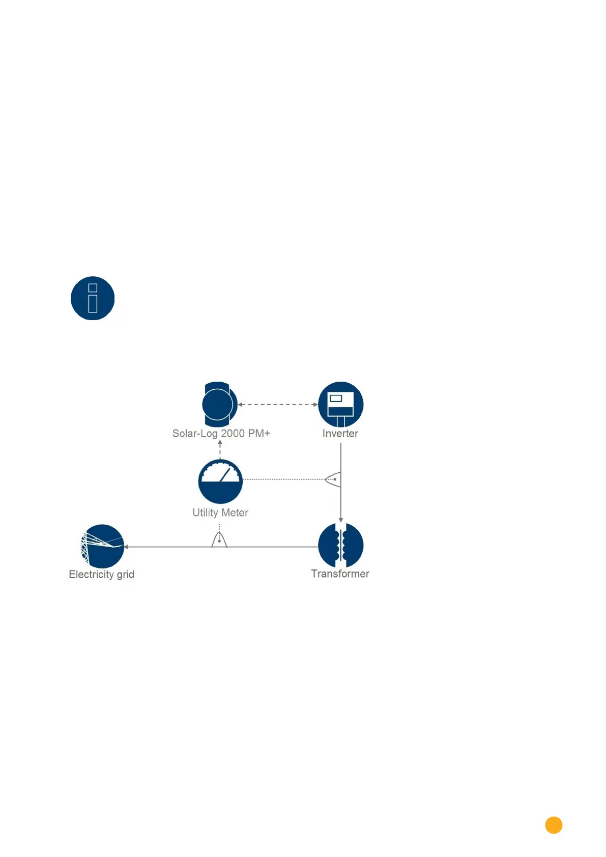
Reactive Power Management
The Solar-Log™ Utility Meter is linked to the Solar-Log™ via the RS485 bus and continually transmits the
measured voltage values to the Solar-Log™. The measured values can be recorded at either the low or me-
dium voltage side (when the corresponding converter and its configuration are present). Using the stored
characteristic curve the Solar-Log™ continually calculates the reactive power to be supplied and controls
the connected inverter accordingly.
Note!
Information on connecting and configuring the Utility Meter is found in the „12.8 Installa-
tion Utility Meter (only Solar-Log 1000 and 2000)“ section.
Fig.: Q(U) control function diagram
Type of characteristic curve section
Using this menu item a characteristic curve specified by the grid operator can be stored. In principle a dis-
tinction is made here between a 2 point and a 4 point characteristic curve.
2-point characteristic curve
By selecting "2-point characteristic curve" it is possible to define a characteristic curve using two points.

 Loading...