6-2
1-1-2. Precautions
1. Switch settings
Adjust the switches to the following positions without loading the
cassette tape unless otherwise specified.
1) Camera/video power switch
Operation switch block ·············································· Camera
2) PROGRAM AE switch ················································ AUTO
LCD 2.5" SD-24 board : S991
SD-25 board : S1991
LCD 3, 3.5" PD-76 board : S991
PD-77 board : S1991
3) D ZOOM switch (MENU) ···············································OFF
4) STEADY switch (CF-45/46 board S403) ························OFF
2. Adjustment sequence
Adjust in the given order.
3. Subject
1) Set the camera and pattern box as shown in Fig. 6-1-2.
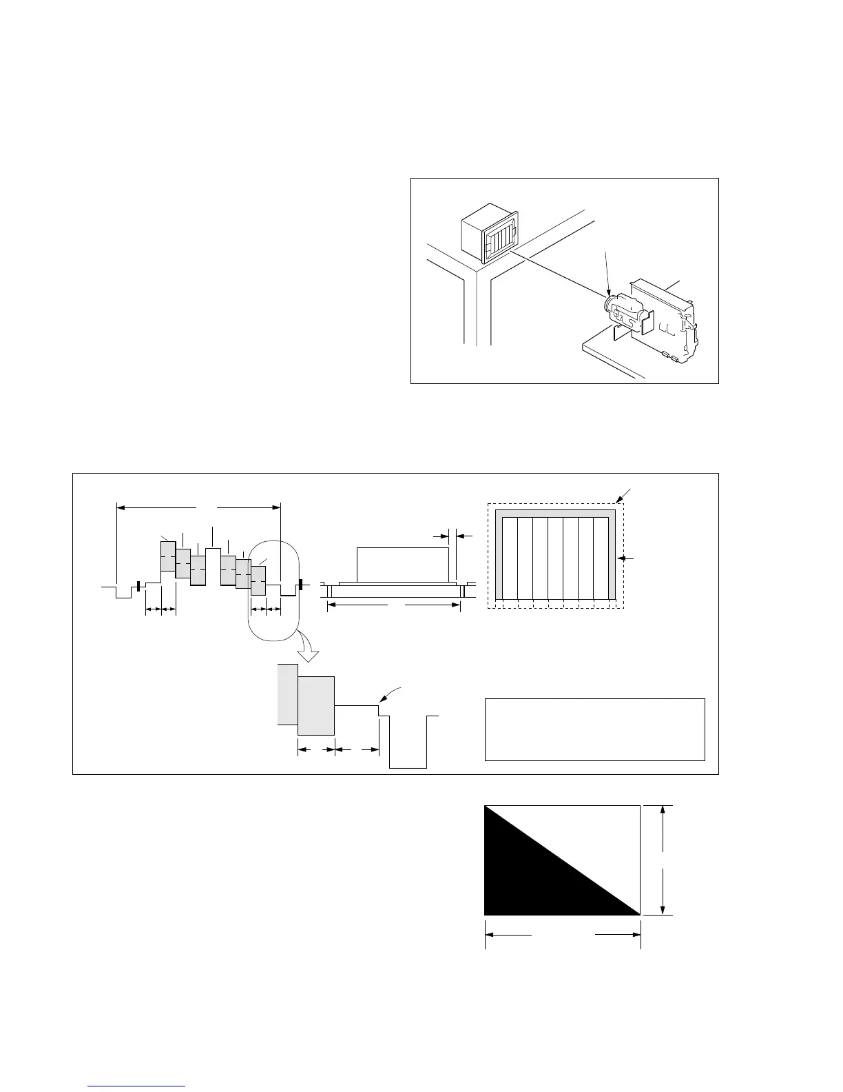
2) Color bar chart (Standard picture frame)
• Adjust the picture frame as shown in Fig. 6-1-3.
• Adjust camera zooming and direction until the camera output
waveform on the oscilloscope shown in Fig. 6-1-3 (a) and the
color picture on the monitor TV shown in Fig. 6-1-3 (b) have
been acquired.
• Maintain this setup until adjustment is complete.
Fig. 6-1-3
4) Chart for flange back adjustment
Join together a piece of white A0 size paper (1189mm × 841
mm) and a piece of black paper to make the chart shown in
Fig. 6-1-4.
Note : Use a non-reflecting and non-glazing vellum paper. The
size must be A0 or larger and the joint between the white
and black paper must not have any undulations.
3) White pattern (Standard picture frame)
Remove the color bar chart from the pattern box and adjust the
camera setup until the white pattern picture frame is the same
size and same position as the color bar chart (the standard
picture frame).
Fig. 6-1-2
Front side of the lens
1.5 m
Pattern box
H
AB A=B BA
Yellow
Cyan
Green
White
Magenta
Red
Blue
Enlargement
0±0.1msec
V
B
A
Difference in level
Fig. a (Video I/O terminal
output waveform)
Fig. b (Picture on monitor TV)
Color bar chart standard picture frame
Yellow
Cyan
Green
White
Magenta
Red
Blue
CRT picture frame
Electron beam scan frame size
Fig. 6-1-4
Black
White
841mm
1189mm
Adjust camera zooming and direction to
obtain the output waveform shown in Fig.
“a” and the TV monitor display shown in
Fig. “b”.