6-77
4-2. 1.5 MHz DEVIATION ADJUSTMENT
(STEREO MODEL)
Purpose : Determines spectrum of the modulated L-ch
(L+R/2 signal) signal during recording.
Adjustment error : Audio signal crosstalk deteriorates and audio
level decreases in both record and playback
modes.
Mode Record
Signal AFM DEV adjustment tool output
signal to left and right channels of
audio input connector
Measurement Point CH1 : TP31 of the AFM DEV
adjustment tool
CH2 : TP3 of the AFM DEV
adjustment tool
Measuring Instrument Oscilloscope
ADD mode
CH2 INV mode
Adjustment Page F
Adjustment Address 2C
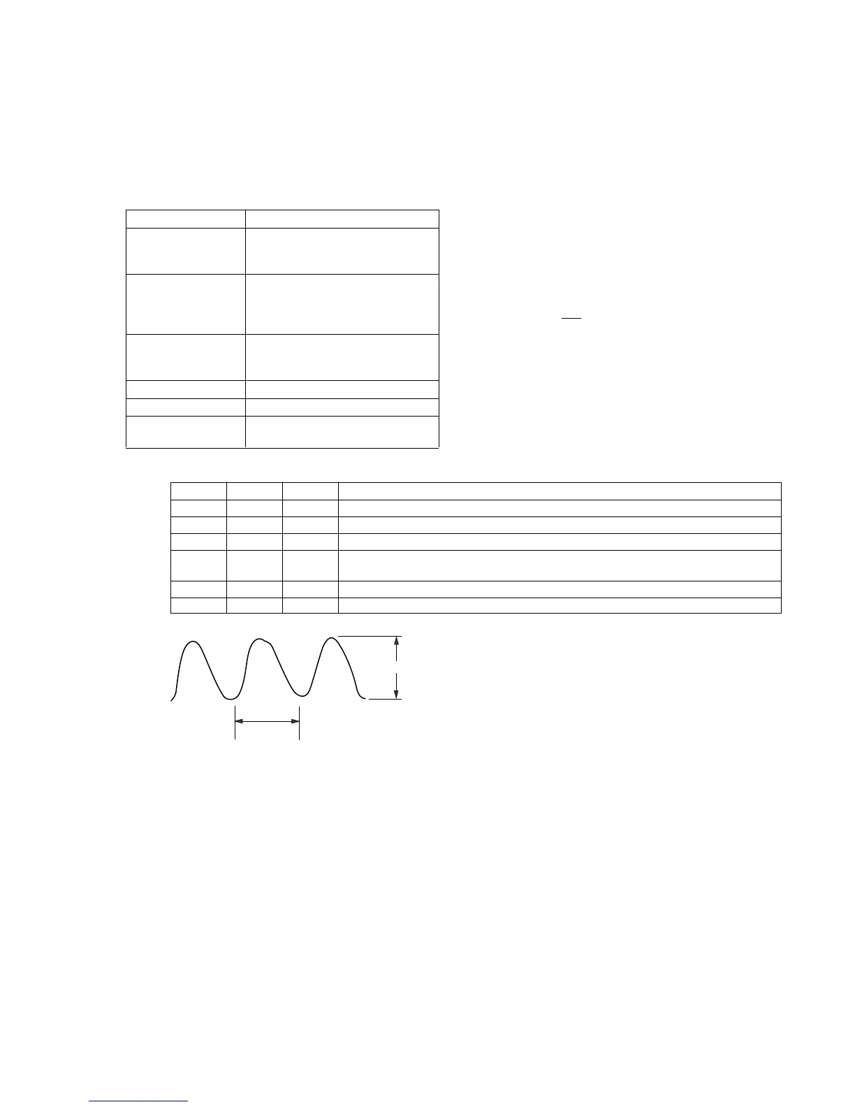
Specification Value Difference (A) between CH1 and
CH2 signals is 40mV or less.
Adjustment procedure:
Order Page Address Data Procedure
1 Select the same vertical sensitivity of CH1 and CH2 of oscilloscope.
2 Set the oscilloscope to ADD mode and set CH2 to INV mode.
3 6 00 01 After setting the data, press the PAUSE button. (Preparation)
4 F 2C Change data using PLAY and STOP buttons so that the audio level difference (A) is
minimized.
5 Press the PAUSE button.
6 6 00 00 After setting the data, press the PAUSE button. (End)
Connection
1) Connect CH2 of the AFM DEV adjustment tool and CN102 of
VC-188 board.
2) Connect the audio output terminals (J1, J2) of the AFM DEV
adjustment tool and Video/Audio input/output connector of the
machine to be adjusted.
3) Connect DC power supply (+7 to +9V dc) to TP28 (DC), and
TP27 (GND) of the AFM DEV adjustment tool.
4) Set the switches of the AFM DEV adjustment tool to the
following positions.
S1 ——— BIL position
S2 ——— NT position
S3 ———
SIN position
About 2msec
A