6-60
3-4. SYSTEM CONTROL SYSTEM
ADJUSTMENTS
1. Battery down voltage adjustment
Purpose : Sets the end voltage of battery discharge.
Adjustment Error :Usable period of a battery will be shortened,
or picture will be distorted at the battery end.
Mode Camera record
Subject Any subject
Measurement Point LCD display of the adjustment
Measuring Instruments remote commander
Adjustment Page F
Adjustment Address 26, 27, 28, 29, 2A
Note 1 : Set the AUTO FOCUS to OFF (MANUAL).
Adjustment procedure:
Note 2 : Refer to the “Hexadecimal-Conversion Table” on page
6-12 , or 〈Conversion between the hexadecimal number
to decimal number〉 and 〈How to convert the decimal
number to hexadecimal number〉 on page 6-13 of the
Service Manual, conversion between decimal number s
and hexadecimal numbers.
2. Battery down voltage check
Connection : Same connection as item “1. Battery down
voltage adjustment”.
Order Page Address Data Procedure
1 Adjust the output voltage of the regulated power supply so that the digital voltmeter
indicates 6.10 ± 0.01Vdc.
2 Insert a cassette and enter the camera recording mode. (CAM REC) After CAM REC is
stabilized (after elapse of about 5 seconds or more), proceed to the next step.
3 6 00 01 After setting the data and press the PAUSE button of the adjusting remote commander.
4 Adjust the output voltage of the regulated power supply so that the digital voltmeter
indicates 5.50 ± 0.01Vdc.
5 2 00 01 After setting the data and press the PAUSE button of the adjusting remote commander.
6 2 39 Read the data displayed on the adjustment remote commander. This data is named Dref.
7 F 2A After setting the data Dref and press thePAUSE button of the adjusting remote commander.
8 Convert Dref into the decimal number. The result decimal number is Dref '. (Note 2)
9 Calculate the following equation (decimal calculation) to obtain the following adjustment
data (decimal number). Convert the adjustment data into hexadecimal numbers
respectively, and set the hexadecimal data into the respective adjustment addresses.
F (Note2) After setting the data, be sure to press the PAUSE button of the adjusting remote
commander.
26 Address : 0F D
0F ' = Dref '+ 19
27 Address : 0E D
0E ' = Dref '+ 16
28 Address : 0D D
0D ' = Dref '+ 12
29 Address : 0C D
0C ' = Dref '+ 6
10 2 00 00 After setting the data and press the PAUSE button of the adjusting remote commander.
11 6 00 00 After setting the data and press the PAUSE button of the adjusting remote commander.
12 Turn off the main power.
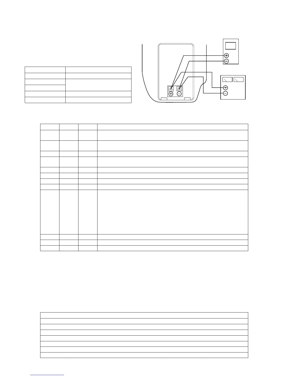
Digital voltmeter
Regulated power supply
(6.10 ± 0.01Vdc)
Battery attachment
block
Order Procedure
1 Adjust the output voltage of the regulated power supply so that the digital voltmeter indicates 6.10 ± 0.01Vdc.
2 Insert a cassette and enter the camera recording mode. (CAM REC)
3 Adjust the output voltage of the regulated power supply so that the digital voltmeter indicates 5.53 ± 0.01Vdc.
4 Confirm that the battery down indication i on the TALLY LED and EVF flashes at the rate of 0.8Hz.
5 Adjust the output voltage of the regulated power supply so that the digital voltmeter indicates 5.25 ± 0.01Vdc.
6 Confirm that the battery down indication i on the TALLY LED and EVF flashes at the rate of 3.2Hz.
7 Press the START/STOP key. (CAM STBY)