6-30
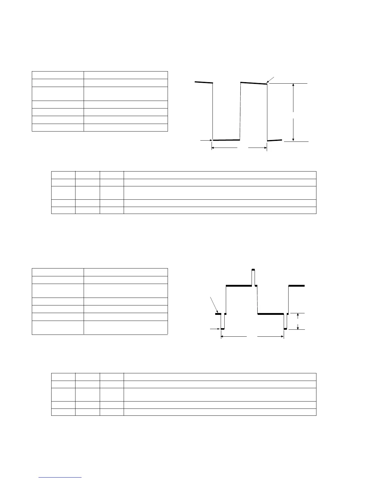
19-4. BRIGHT adjustment (VF-110 board)
Purpose : Adjust brightness of EVF screen (appearance)
Adjustment error : The EVF picture will be close to saturated
picture (white washing) or black compression.
Mode Playback
Signal Signal
Measurement Point CN702 pin 3 (G OUT) on
VF-110 board
Measuring Equipment Oscilloscope
Adjustment Page F
Adjustment Address CC
Specification A=7.0 ± 0.1Vp-p
Connection
1) Connect CN702 pin 3 and pin 2 (EVF GND) using a 3300Ω
resistor (1-249-423-11).
Adjustment Procedure:
Related adjustment items
[White Balance Adjustment]
19-5. CONTRAST adjustment (VF-110 board)
Purpose : Adjust contrast of the EVF screen.
Adjustment error : The EVF picture becomes dull (white washing)
or close to saturated image.
Mode Playback
Signal Signal
Measurement Point CN702 pin 3 (G OUT) on
VF-110 board
Measuring Equipment Oscilloscope
Adjustment Page F
Adjustment Address D1
Specification A=2.0 ± 0.1Vp-p (NTSC)
A=2.0 ± 0.1Vp-p (PAL)
Connection
1) Connect CN702 pin 3 and pin 2 (EVF GND) using a 3300Ω
resistor (1-249-423-11).
Adjustment Procedure:
Order Page Address Data Procedure
1 6 00 01 Set the data. (Preparation)
2 F CC Change the data until the voltage difference (A) between the inverted waveform's pedestal
and the non-inverted waveform's pedestal satisfies the specification.
3 Press the PAUSE button.
4 6 00 00 Set the data. (End)
Order Page Address Data Procedure
1 6 00 01 Set the data. (Preparation)
2 F 4B Change the data until the voltage difference (A) between the 50% all white signal and the
pedestal satisfies the specification.
3 Press the PAUSE button.
4 6 00 00 Set the data. (End)
A
2H
Pedestal
level
Pedestal level
A
2H
Pedestal
level
White 50%
Level