6-34
20-2. VCO adjustment
Purpose : Sets the VCO free-run frequency.
Adjustment Error :Incorrect picture on EVF
Mode Stop
Signal No signal
Measurement point CN804 pin 4 (HDB) (Type 1, 4)
CN1804 pin 4 (HSY) (Type 2, 3)
Measuring equipment Frequency counter
Adjustment page F
Adjustment address DE
Specification f=15625 ± 30Hz (PAL) (Type 1, 2, 4)
f=15734 ± 30Hz (NTSC) (Type 3, 4)
Adjustment procedure:
Note :
Order Page Address Data Procedure
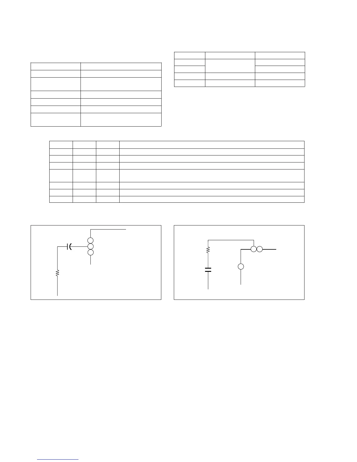
1 Remove C183/C1804 (1µF capacitor) (Note)
2 Press the DATA SCREEN button of the remote commander to disappear the display.
3 6 00 01 After setting the data, press the PAUSE button. (Preparation)
4 F DE Change data using the PLAY and STOP buttons until the oscillating frequency satisfies
the specification.
5 Press the PAUSE button.
6 6 00 00 After setting the data, press the PAUSE button. (End)
7 Connect C183/C1804 (1µF capacitor) (Note)
35
SYNC SEP
36
37
〈IC1801〉
C1804
1µF
R1815
560
TYPE 1, 4 (PD-76/SD-24 board)
TYPE 2, 3 (PD-77/SD-25 board)
38
SYNC SEP
37
39
IC801
+
1µF
16V
R821
R819
560
C183
R821 : SD-24 board
R819 : PD-76 board
Fig. 6-1-17
Type 1
Type 2
Type 3
Type 4
LCD size
2.5 inch (PAL only)
3.0 inch (NTSC)
3.5 inch (NTSC/PAL)
LCD board
PD-74/SD-24
PD-75/SD-25
PD-77
PD-76
No mark : Type 1, Type 4
〈 〉 : Type 2, Type 3