6-74
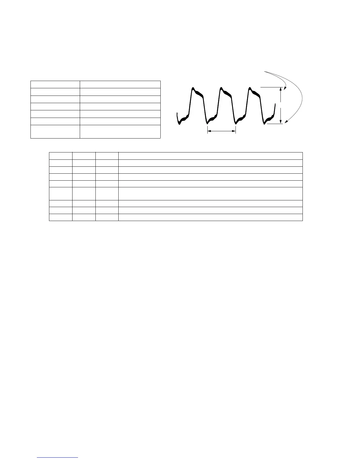
3-16. REC Y LEVEL ADJUSTMENT
Purpose : Maintains a constant level of Y FM, chroma
AFM and ATF signals when recording on tape.
Adjustment error : (If level is low) Poor S/N of playback picture
(If level is high) Black streaking noise appears.
Connection : Connect CN102 pin 8 (RF SWP) to GND.
Mode CAM-REC (SP)
Signal No signal
Measurement Point CN102 pin 2 (check connector)
Measuring Instrument Oscilloscope (Note)
Adjustment Page F
Adjustment Address 35
Specification Value A=132 ± 5mVp-p (PAL)
A=155 ± 5mVp-p (NTSC)
Adjustment procedure:
A
0.208 µsec
Center of luminance
line width
Note : Use the MP type tape. If an oscilloscope has the bandwidth
limiting switch, set to on position.
Order Page Address Data Procedure
1 6 00 01 After setting the data, press the PAUSE button. (Preparation)
2 Insert the MP tape to establish record mode.
3 6 01 Read the data of page : 6, address : 01, and record it.
4 6 01 43 After setting the data, press the PAUSE button.
5 F 35 Change data using PLAY and STOP buttons so that the REC Y RF level (A) satisfies the
specification.
6 Press the PAUSE button.
7 6 01 Set the data which is recorded in step 3 to this address and, press the PAUSE button.
8 6 00 00 After setting the data, press the PAUSE button. (End)