6-75
Vo
700
( )
3-17. REC C LEVEL ADJUSTMENT
Purpose : Maintains a constant chroma level when
recording on tape.
Adjustment error : If level is low, overall S/N deteriorates.
If level is high, S/N of Y signal at deep color
deteriorates and white streaking noise appears.
Mode CAM-REC
Signal White pattern (See page 6-2)
Measurement Point • CN102 pin 2
(Check connector)
• VIDEO output terminal
(terminated in 75Ω)
Measuring Instrument Oscilloscope
Adjustment Page F
Adjustment Address 37
Specification Value
A= 23.5 × mVp-p ± 2mVp-p
(PAL)
A= 32.4 × mVp-p ± 2mVp-p
(NTSC)
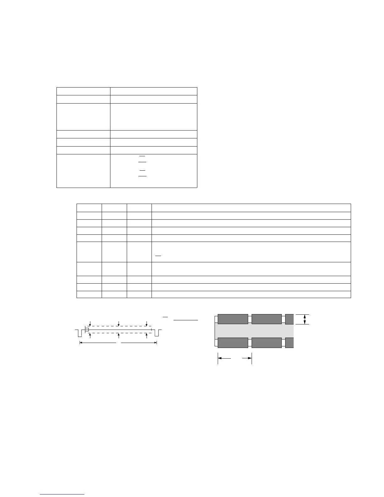
Adjustment procedure:
Vo
714
( )
V
1
V
2
V
3
V
()
V
O =
V
1
+ V
2
+ V
3
3
VIDEO OUT Signal
V
A
Order Page Address Data Procedure
1 Shoot the all white pattern to the full picture frame.
2 6 00 01 After setting the data, press the PAUSE button. (Preparation)
3 6 01 Read the data pf page : 6, address : 01, and record it.
4 6 01 45 After setting the data, press the PAUSE button.
5 Measure the chroma output level of the VIDEO OUT connector. Obtain the average
value of three points (beginning, middle, end) of a vertical period. Call the average value
Vo (mV).
6 F 37 Change data using PLAY and STOP buttons so that the REC signal at CN102 pin 2
amplitude (A) satisfies the specification.
7 Press the PAUSE button.
8 6 01 Set the data which is recorded in step 3 to this address and, press the PAUSE button.
9 6 00 00 After setting the data, press the PAUSE button. (End)