6-33
[Power supply voltage adjustment]
Adjust the power supply voltage to be input to the battery terminal
so that the voltage across PD-74〈75〉76〈77〉 board CN802 〈CN1802〉
pins 3 (LCD UNREG) and pins 4 or 5 (UNREG GND) is 6.5 ±
0.1Vdc.
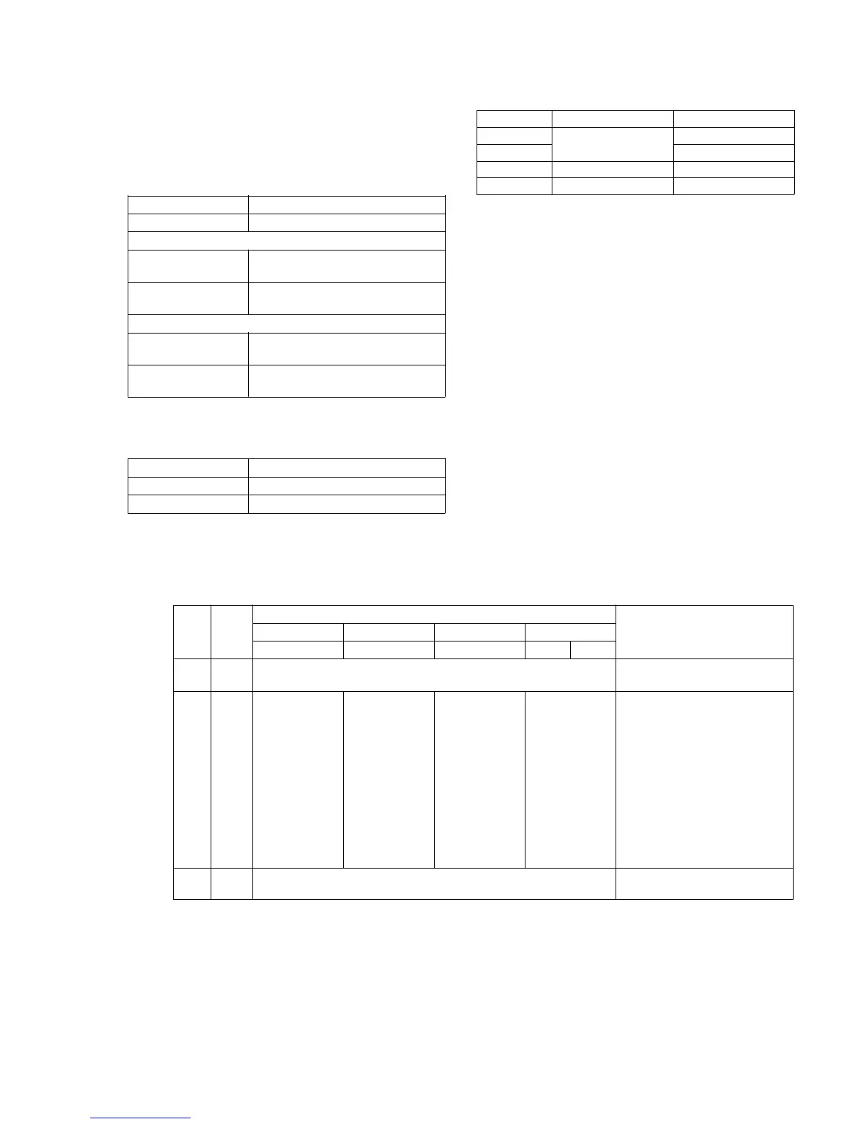
Power supply voltage check
Subject Any subject
Measuring equipment Digital voltmeter
D 3.1V check
Measurement point CN801 〈CN1801〉 Pin 7
(SD-24〈25〉, PD-76〈77〉)
Specification 3.1 ± 0.1Vdc
(GND : CN801 〈CN1801〉 Pin 8)
PANEL 4.9V check
Measurement point CN802 〈CN1802〉 Pin 6
(PD-74〈75〉76〈77〉)
Specification 4.65 ± 0.05Vdc
(GND : CN802 〈CN1802〉 Pin 7)
20-1. EVR initial data input
Mode Stop
Signal Any signal
Adjustment page F
Note : Do not rewrite the EE PROM data except when it is
necessary such as replacement of SD-24〈25〉, PD-76〈77〉
board IC802 〈IC1802〉.
Modidication procedure:
Order
1
2
3
Page
6
F
6
Address
00
D8
D9
DA
DB
DC
DD
DE
DF
A0
A1
A2
A3
00
Data
TYPE1 TYPE2 TYPE3 TYPE4
PAL PAL NTSC NTSC PAL
01
99 5A 80 8C 91
60 5F 71 C5 67
85 5D 65 6A 7D
7F 70 66 77 79
75 5F 60 6E 6C
A9 95 94 89 8C
A8 90 84 9B 79
88 30 36 AF A4
(80) 65 64 (80) (80)
(80) 7B 71 (7F) (7F)
(FF) (FF) (FF) (FF) (FF)
(02) (04) (05) (07) (08)
00
Procedure
After setting the data, press the
PAUSE button. (Preparation)
Set each data to each address,
and press the PAUSE button.
After setting the data, press the
PAUSE button. (End)
Type 1
Type 2
Type 3
Type 4
LCD size
2.5 inch (PAL only)
3.0 inch (NTSC)
3.5 inch (NTSC/PAL)
LCD board
PD-74/SD-24
PD-75/SD-25
PD-77
PD-76
No mark : Type 1, Type 4
〈 〉 : Type 2, Type 3
Values in parenthis ( ) are fixed values.