6-31
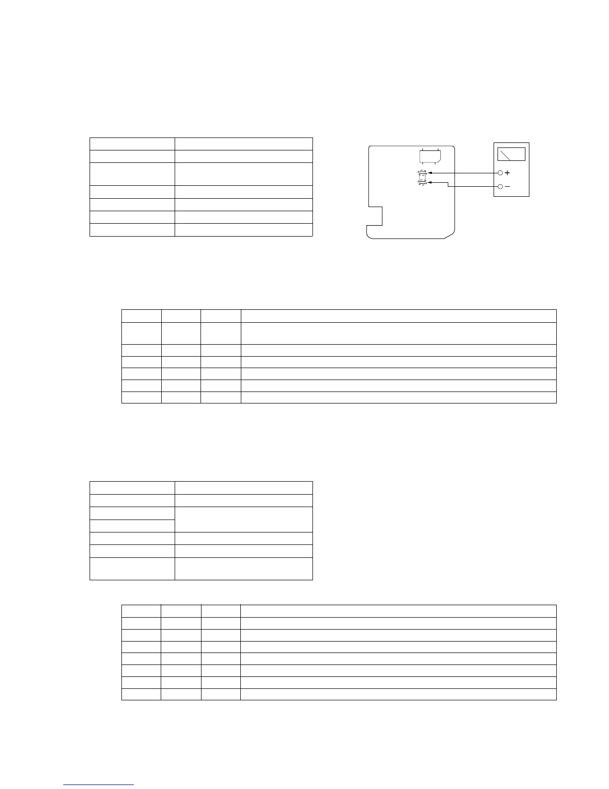
19-6. Back light Current consumption adjustment
(VF-109 board)
Purpose : Set brightness of the back light (fluorescent
lamp) to a constant level.
Adjustment error : The EVF screen will become too dark or too
bright.
Mode Playback
Signal No signal
Measurement Point The pattern land from which R891 is
removed
Measuring Equipment Current meter
Adjustment Page F
Adjustment Address D3
Specification 45 ± 2mA
Note 1 : Perform this adjustment after 30 seconds of warm up after
the power is turned ON.
Note 2 : Remove R891 before adjustment, and return R891 after
adjustment.
Adjustment Procedure:
19-7. White balance adjustment
Purpose : Calibrate the white balance.
Adjustment error : The color reproduction of the EVF screen
becomes poor.
Mode Playback
Signal Any signal
Measurement Point Check white balance on the EVF
Measuring Equipment screen.
Adjustment Page F
Adjustment Address CF, D0
Specification The EVF screen must not have any
colors.
Adjustment Procedure:
Order Page Address Data Procedure
1 Remove R891 from the VF-109 board.
Connect an ammeter to the pattern lands from which R891 is removed.
2 6 00 01 Set the data. (Preparation)
3 F D3 Adjust the current value to the specification.
4 Press the PAUSE button.
5 6 00 00 Set the data. (End)
6 Reconnect R891.
Order Page Address Data Procedure
1 6 00 01 After setting the data, press the PAUSE button. (Preparation)
2 F CF 7A After setting the data, press the PAUSE button.
3 F D0 6A After setting the data, press the PAUSE button.
4 Confirm that the EVF screen has not color at all.
5 F CF, D0 If the EVF screen has any colors, change the data until the EVF screen has any colors.
6 Press the PAUSE button.
7 6 00 00 After setting the data, press the PAUSE button. (End)
Note : Connect ammeter to thee lands where R891 is removed.
Fig. 6-1-14
Current meter
A
VF-109 board (side B)
CN852
R891