6-26
18. Electronic viewfinder system adjustments
(VF-102 board)
Note : About 2200V dc is applied to CRT anode and about 200
Vdc to the grid. Be careful not to touch them. If hand
touches them, there is danger of electric shock
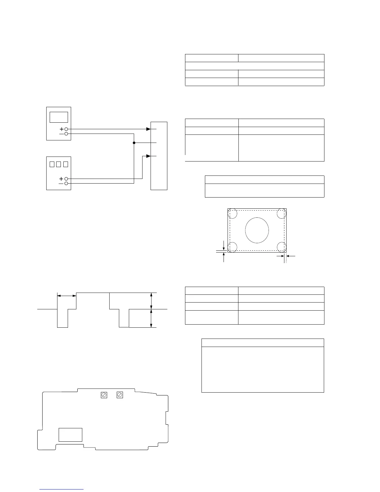
Preparation :
1. Disconnect a flexible board from CN901 on VF-102 board.
2. Connect equipments as follows.
Required signals
1. Monoscope signal
Output amplitude: 1.0 Vp-p (75Ω terminated)
Horizontal resolution: 600 TV lines or more
Vertical resolution: 350 TV lines or more
2. Dot pattern signal
Output amplitude 1.0 Vp-p (75Ω terminated)
3. Contrast signal
Output amplitude 0.5 Vp-p (75Ω terminated)
fH : 15.750kHz (NTSC)
15.625kHz (PAL)
fV : 60Hz (NTSC)
50Hz (PAL)
Others: Complies with NTSC and PAL.(Refer to Fig. 6-1-12.)
Fig. 6-1-11
1
2
4
5
3
Following signals
+4.85Vdc
CN901
pattern
generator
regulated dc
power supply
9µS
0.2V
0.3V
18-1. Power supply voltage check
Measuring Instrument Digital voltmeter
EVF5V
Measurement Point CN901 Pin 1
Specification Value 4.65 + 0.1Vdc
18-2. Horizontal and vertical position
Purpose : Maintains horizontal position.
Adjustment error : Horizontal position cannot be maintained.
Signal Monoscope signal
Adjustment RV905
Specification Value Overscan 3.5 ± 3.5%
(horizontal) (one side)
Overscan 4.5 ± 5% (vertical) (one
side)
Adjustment procedure:
Order Procedure
1 Confirm that the horizontal and vertical picture sizes
satisfy the specification values.
18-3. BRIGHT adjustment
Signal Monoscope signal
Measurement Point CRT screen
Adjustment RV904
Specification Value Each step of gray scale signal is
displayed clearly.
Adjustment procedure:
Order Procedure
1 Adjust RV904 until each step of gray scale signal is
clearly display. (For the brighter region, do not
increase brightness to such an extent that the cross-
hatch at the center of monoscope signal becomes
flared. For the dark region, do not decrease brightness
to such an extent that the first step (the darkest step)
and the third step cannot be identified.)
RV904
1 5
CN901
RV905
4.5%
3.5%
VF-102 BOARD (SIDE A)
Fig 6-1-12